Hello Fellow Yuneec Pilot!
Join our free Yuneec community and remove this annoying banner!
Sign up

Camera wires broke off circuit board

  • Like
Reactions: Motor_Fan
Yesterday, I had my first crash as my son crashed my Blade Chroma into the roof of our house.

Long story short everything is ok except for this exact problem as pictured in the photos.

I have the CG03 camera and gimbal but three wires hanging from the part that you slide to connect to the drone. Kind of confused after going through all of this because looking at the parts I think what I'm looking at is actually the compass unit based on looking at this part YUNEEC Compass Module Unit

Does that sound about right? Sorry, VERY new to this world.
That looks like something that goes inside the bird. Can you post pics similar to what I did? It'll help us help you.
 
And as fate would have it, did mine in as well on Sunday - Aerial landing in a tree. No reason, video and controls cut out 5 seconds or so before crash.

Ripped all thee wires off Gimbal, and one (PWM)) took the imprinted copper pad and wire off the circuit board all the way to the chip/transistor/tiny rectangle on the board. Right before I left the house I removed the pigtail. Everything still works after recovery and reassembly. Just need to solder the wires back onto the circuit board.
 
Well that sucks. Glad everything else seems fine. This is proving to be a serious weak point with this bird. I'm glad it does come apart though, as it seems to save the gimble and camera.

It just make the heart skip a beat when you see those wires hanging there.
 
From what I have gathered, the circuit board, and camera are a mated pair. If the board get's trashed you can not just drop in a new one.

More and more I am leaning towards putting a breakaway point mid wire. I need to go to a hobby shop, or have someone spec out the male and female pins that I can put on these wires. I am used to dealing with wire no smaller than 18ga. Even my smallest automotive connector parts are larger in diameter than all three wires.

good idea , breakaway wire connector .
 
  • Like
Reactions: Fleamac
I placed an order for a bunch of 2.5mm jumpers the day before you posted George. I am going to color code the three terminals, route the wires a little different and zip tie them to the case so when it does break away, it does not jerk on the boards, just pulls the pins out of the sockets, and won't matter which direction is it getting pulled.

I'll post pics when I am done. I just hope I can get the copper pad and inlaid wire back down OK. I may have to tap into the back of the pigtail plug.
 
  • Like
Reactions: Fleamac
Hey gang, I love how helpful everyone is, but as a complete newbie to the electronic side of this I'm lost on how to "reconnect to my circuit board." I know HOW to do it, but just not where to connect the wires.

Here are shots of my camera and the broken wires.

24735301622
24557681030


1. What does this cable provide for functionality? I'm curious.
2. Do the wires actually need to be soldered back on to the circuit board or am I missing something that plugs in?

Thank you for any help. Hoped to fly my drone in the snow today, but without this connection I'm not sure what I'd not be able to do.

-C.C.
 
if you did not break the little pigtail harness that goes from the gimbal to the Q500, then you should be able to still get video without what I suspect are the same broken wires as shown in this thread.

If you do not have that little pigtail, or it got damaged also, you have a problem.

We will see if you get your pictures uploaded.
 
Hey George! Do you have another link for the GoPro Type?

Sorry, but not being a GoPro user I've not looked into that.

However, I would not think that the gimble connection would be any different for the GoPro, since both gimbles plug into the same place on the craft itself.

RodeoGeorge
 
OK...I did the ol' "Found a tree, knocked the gimbal off, broke the wires" thing. I was going to perform the repairs and put in a break away connection mid point in the leads from the gimbal mount to the gimbal so no more ripped wires off the circuit board the next time I crash.

So I finally got a hold of all the crap I needed to perform the repairs, and that one little inlaid wire that came loose from the circuit board, broke off. And everything was going so well too.

Getting ready to start.

20160209_193815.jpg


Finished the break away wires for the gimbal mount
20160210_025040.jpg


The inlaid wire and copper pad that ripped loose of the board.
20160201_131108.jpg


Got 2 of the lower wire soldered on, then that one that pulled the pad and wire loose from the board broke.
20160210_025242.jpg


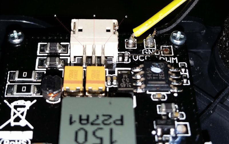
SO - The current plan is to solder the PWM wire to the back of the pigtail connection port, but I need to know which lead is what.
Camera%252520board.jpg

Edited - Found the info - Thanks George for the tip
Left to right,
A ~ GND
B ~ VCC
C ~ PWM


So now that I found out which pin on the back of the connector I need to go to...

20160210_125226.jpg


Ran the wires under the board and up from behind, then through the cover.

20160210_125237.jpg


20160210_125332.jpg


Here is is all assembled and connected. The pins keep a good connection, and should pull free in the event of another gimbal mount separation. No I did not do a inertia test to verify. I will take it on faith that the solder joints and the wires will hold longer than the pins in the sockets.

Probably going to void the warranty on the other (yes, I bought a another Q500 set) and do this pre-emptively, so the board does not get damaged by ripping the solder joints out.

20160210_125759.jpg


I first tried to test in my steady grip, and everything was working, but the app. I then attached it to my Q and everything works as normal.
 
Last edited:

New Posts

Members online

No members online now.

Forum statistics

Threads
20,973
Messages
241,785
Members
27,347
Latest member
erothots