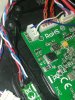
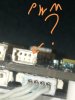
Hello everybody ! Im after a pinout schematic for cgo2gb and q500. As far as I know there are 4 wires going from camera to the drone(12v and pwm ?) . Thanks in advance ")
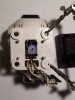
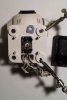
Bonus question- Has anyone got a clue about the yaw motor pot correct position ? from my understanding the wiper should be in middle (reading 5 k ohms from both sides, to the wiper pin) when camera yaw motor is in the middle.
Bonus question- Has anyone got a clue about the yaw motor pot correct position ? from my understanding the wiper should be in middle (reading 5 k ohms from both sides, to the wiper pin) when camera yaw motor is in the middle.
Last edited: