- Joined
- Jun 28, 2016
- Messages
- 158
- Reaction score
- 18
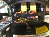
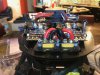
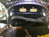
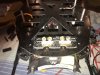
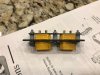
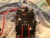
Well, I decided to install some XT-90 connectors into my H920+ so I don't have to mess with adapters. I upgraded the power wire to the bistro board to 10awg wire as well. I built the mount out of carbon fiber and screwed it to the factory batter connector mounts. It worked out very well and is very solid!