Hello Fellow Yuneec Pilot!
Join our free Yuneec community and remove this annoying banner!
Sign up

Yuneec's software for gimbal calibrations

Joined
Mar 4, 2019
Messages
400
Reaction score
211
Age
55
Is anyone interested in helping put together a manual for the calibration software I shared a while back?
I am slow but dedicated to helping others with their broken gimbals lying around.
 
There is an instruction video from Yuneec shoeing the CGO3+ calibration.


They use a program called "YGroundControl". This looks different to the "GB-SET V39 ENGLISH". This one is used to calibrate the CGO3 in this video:


However, I didn't get GB-SET V39 ENGLISH to work with my CGO3. But I have only one and thus do not want to do experiments that may brick my gimbal. With CGO3+ no connection is possible with this tool.

br HE
I am going to get up with the guys again. Maybe if I hound him he will share it.
 
There is an instruction video from Yuneec shoeing the CGO3+ calibration.


They use a program called "YGroundControl". This looks different to the "GB-SET V39 ENGLISH". This one is used to calibrate the CGO3 in this video:


However, I didn't get GB-SET V39 ENGLISH to work with my CGO3. But I have only one and thus do not want to do experiments that may brick my gimbal. With CGO3+ no connection is possible with this tool.

br HE
I was able to get it to work with one gimbal so far. So I can verify that it does work but is touchy. I also found some interesting stuff about the cgo3P gimbal. Yuneec used the STM32 chip on the main board. I have been working with these chips for a long time doing different stuff. STM Electronics offers a gimbal calibration tool for all gimbals with their chip. You can get the software from their website. I have it but have not tried it yet.
 
I have been reading up on the stm32 f373cct6 microprocessor used with the cgo3P gimbals. We can use the STM32 utility to read the values directly from the chip itself. You can also write new values to the chip using their STM cube programmer. There is also a way to connect and read the encoder values coming into the chip. I have a working cgo3p gimbal and plan on reading the stock values from it to get an idea about the encoder's settings. I am going to move it around while reading the values to see what happens. This will take some time but I will post my results. The data sheet for this chip says it has a USB communication. There is a USB connection on the camera board but I am not sure if Yuneec uses this to connect with the gimbal. I need to find the pinout of the chip and see where the USB is connected. The gimbal software they have for their board may read the chip on the cgo3p but I would not use the firmware. I also found out that Yuneec paired up with Leica cameras and used their cameras with the Typhoon H. I am also looking at the code for the v39 software to see if it can be relatable to use with other gimbals. There are a lot of notes listed in the code from the engineer.
 
What chip are you talking about? The AS5600 angle sensor? It has no USB but I²C. There is a good description in the datasheet how to set bounds/angle programming. I can read raw data from it using an Raspberry Pi.
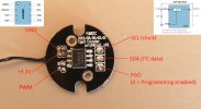
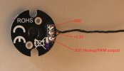
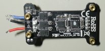
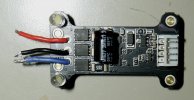
Here are the pins to access:
AS5600_fr.JPGAS5600_bk.JPG

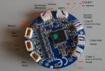
Here are the debug ports from the gimbal main board:
CGO3Plus_Pinlayout3.jpg

The USB port on the camera is out of service. There are pads for it on the PCB but empty on nearly all boards I have seen. CGO3P only supports the UART.

br HE
 
What chip are you talking about? The AS5600 angle sensor? It has no USB but I²C. There is a good description in the datasheet how to set bounds/angle programming. I can read raw data from it using an Raspberry Pi.
Here are the pins to access:
View attachment 29959View attachment 29958

Here are the debug ports from the gimbal main board:
View attachment 29960

The USB port on the camera is out of service. There are pads for it on the PCB but empty on nearly all boards I have seen. CGO3P only supports the UART.

br HE
The gimbal main board has the stm32 chip.
 
I am curious if we can use the STM Cube programmer to read the STM chip on the main board. I have a few lying around and will try it. I am guessing I will have to use a JTAG to communicate with them.
Magnet position is important. If the magnet is turned wrong it will throw everything off. Are you using the Raspberry Pi like a JTAG debugger?

This has never been about owning some software. This has always been about curiosity for me. I am looking at the programming used on the v39 software also. I do code a bit but am really slow at it. If someone knew more about C++ or Java they could probably put something together that would work. What protocol does the CGO3P use?

Maybe we could use Github's copilot to write the code to communicate with the gimbal.
 
Last edited:
The STM32 from the flight controller is read protected. No way to get the SW. I have tried to read the original bootloader without success. If you overwrite the bootloader you can install another SW but then there is no way back. For the STM32 I use the debug port and ST-Link V2.
Never tried to connect to gimbal board but it is worth to try. But I doubt we can read something there.

To access the AS5600 I use the I²C port on the front side. I think it is not needed to program something here. For me it looks like the build-in calibration started from ST16 will find the endpoints and set it. I have also the feeling that this part of calibration sets the values for the IMU (MPU6050 or the one in the black box).

By the way, did someone opened the black box IMU? What is in? And second: Has someone the gimbal FW 1.27 dedicated to the black box IMU?

br HE
 
I hit the jackpot!
I searched the Yuneec encoder's chip number AS5600 and found some GREAT information.
I haven't tried to read the stm32 yet but I will. I am going to use the same st link v2 and read just the chip on the board.
Take a look at the video here-
and

I have a cgo3p that was bouncing all over the place. I found the magnets were broken and replaced them. The gimbal now doesn't have any beeping codes but still shaking. I marked one of the magnets and tried turning it at 2mm increments and testing it. I now have it pretty steady and working but still a small vibration. So the magnet position plays a HUGE role in the gimbal's operations. The video I shared shows how to write information to the encoder's chip and how to align the magnet's position. Do you know if the gimbal board stores the encoder's information? If so, as long as I can read and write to the STM32 chip, I will be able to write new positions to the chip through the st link.
I also found another former employee from Yuneec. I sent an email and am waiting for his reply
 
Last edited:
The STM32 from the flight controller is read protected
It seems there is a way around this. I will see if I can find it again. I had one that was read-protected but found some software that would unlock it. I just don't remember which one it was.
I think it is the J-Link for stm32 and JLinkSTM32.exe There is a way to get around it through a serial connection.
And-
 
Last edited:
Black box? I am not sure what you mean.
The encoder does hold settings for the magnets. I really feel this is our key.
The raw data you read from the as5600 is what I want to see. Do you have a copy? Not all of them will be the same if I am correct.
Here is an Arduino library that can be used to read the as5600 live.
 
Last edited:
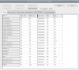
With my Raspberry Pi tool I can only read the register from AS5600, but if needed it is not so difficult to add write function.
View attachment 29964
These numbers say a lot. This is what I expected.
Give me a few days to research this but I think we can use this information to set something up. If someone who knows Java or C++ better than I do, could take a look at the programming software we have, they could probably set up a nice communication app for us. I am limited when it comes to coding but I do code a little, probably just enough to get me in trouble.

I've been pretty busy the last couple of days but I will work on this over the weekend and post my results early in the coming week.

What Raspberry Pi tool are you using? I don't recognize the software you are using either. Did you write it yourself?

Our main problem is the fact that most have moved away from Yuneec by now or have lost interest in their products. This gives us limited help. The good news is that the die hard Yuneec guys, like myself, WTF, and you are still here and willing to put in the time to resolve these issues.

I noticed an ad on eBay from a seller who listed the magnets for these encoders. He had them listed as yaw, roll, an pitch magnets being three different sizes. Has anyone else noticed a difference in these magnets?

One last thought, the name of these cameras are CGO. Did Yuneec name the camera because of its programming language? CGO or GO programming?

3AAQAIAAAA4EjdzjqwKfQkALYcYeFAFT2ZuqJgkEylFj9zQ2xXuylmWapw29Kkb7u8mjLXG69HX9K3IyVN4X5xtb0qszrpNurXjrSyFhOeQN3GMgLP5zNZk6z8s9yIdxR6HnlAzuMELxeuFGrpIUnBBrpkYf9CrhD
 
Last edited:
Take a look at this software.


STM32 MC SDK (motor control software development kit) firmware includes the permanent magnet synchronous motor (PMSM) firmware library (FOC control) and the STM32 motor control workbench (to configure the FOC firmware library parameters), with its graphical user interface (GUI).

STM32 motor control workbench is a PC software that reduces the design effort and time needed for the STM32 PMSM FOC firmware configuration.

The user generates a project file through the GUI, and initializes the library according to the application needs. Some algorithm variables can be monitored and changed in real time.
 
Today I plan on trying to access the STM32f chip through some of the software STM has. I am also going to try and remove one of the chips from an old cgo3p main board.
Wish me luck.
 
I don't think that CGO3 gimbal has FOC ESC's, but maybe. But Yuneec has FOC ESCs. I think it is from a larger gimbal, H920 or so.
Yuneec_FOC_ESC_back.JPGYuneec_FOC_ESC_front.JPG
It has STM32 F303K8 chip and an OPAMP TP1561A for FOC + the 6 MOSFET with 3 drivers. It's just for curiosity - will not help us for CGO3+.
------------------------------
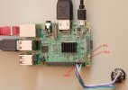
The IMU test program was originally made when I have done investigations regarding the well known IMU problem of the Typhoon H. Later I expanded the functionality to other sensors on I²C bus, among this the AS5600. But it can only read the register.
The program is for 32-bit Raspi OS (Raspi 2, 3, 4 Zero, Zero W). Github: GitHub - h-elsner/MPU6050-test-tool: MPU6050 test GUI for raspberry Pi

AS5600_pi_kl.JPG
I have added the sensor alone but I think we can access it too when still mounted on gimbal. The I²C interface is easily accessible on front side, only ground is hard to find on the front side of the sensor (pictures in #6).

br HE
 

Attachments

  • imu_test.zip
    2.9 MB · Views: 3
  • Like
Reactions: Steve Carr
The readout protection Yuneec used on these STM32 chips is pretty tough. I have not been able to crack it, yet. I am waiting on some leads for my magnetometer so I can read the poles on the magnets. If you don't get the poles in the correct position, you will have issues. The guy from Yuneec said he couldn't find the other software he had. I emailed the head engineer for Yuneec to see if he would respond. I actually offered him 500 dollars for the software and promised I wouldn't share it with many people. Keep your fingers crossed.

**********update********** Yuneec has contacted me through email. They are considering allowing me access to the software. Again, fingers crossed.
 
Last edited:
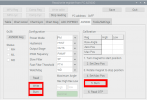
I have not tested yet but some of the functionality is already there. So it could look like when we want to calibrate the AS5600 sensors at the gimbal using I²C interface.
AS5600_Page.png
I will proceed develop if such a tool is needed by someone.

br HE
 

Attachments

  • AS5600_Prog.pdf
    267.8 KB · Views: 6
  • Like
Reactions: cabinfourus
The AS5600 in CGO3+ is not programmed and is freely interchangeable. There is a gap in readings, so the position of the magnet is important. Fine-tunes are written in the ST's EEPROM.
 

New Posts

Members online

No members online now.

Forum statistics

Threads
20,977
Messages
241,831
Members
27,384
Latest member
TroyBoy