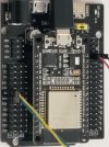
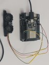
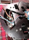
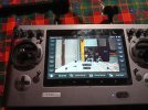
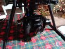
I got the TH OBS module working with an esp32. The minimum detection appears to be ~17" (~43cm), at least with the code I found. Anything closer is still reported as ~17". The numbers appear to be off, but at least it working. If I completely cover the sensor it reports 0", as it should. Next step will be to connect it to the FC.
You are using an out of date browser. It may not display this or other websites correctly.
You should upgrade or use an alternative browser.
You should upgrade or use an alternative browser.
Convert Typhoon H to PixHawk 6C Flight Controller
- Thread starter 1midniterider
- Start date
h-elsner
Premium Pilot
- Joined
- Mar 23, 2016
- Messages
- 2,395
- Reaction score
- 2,156
- Location
- Bavaria / Germany
- Website
- h-elsner.mooo.com
I was looking into an I2C interface when I came across this digital write example. So, I'm not sure what it would fall under.That's intresting. What is the interface from OBS to ESP32? Is it I²C or PWM or analog or ...?
ESP32 HC-SR04 Ultrasonic Arduino
It simply worked as is. It's not PWM, analog or serial. Well, at least I don't think that it is. I'm new to ESP32 programming, so take this with a grain of salt. I tried using an example to detect I2C but, it didn't work, which could be because I didn't use pull-up resistors.
Antenna placement. The cable shielding helped gps and the receiver. However, I'm still getting some interference. There are 3 sources of 2.4GHz transmission, the SR24, the MavLink ESP8266 and Drone ID which is on an ESP32-C3 module. All three are on the underside of the drone. The SR24 is in the original TH location. The other two located about the middle on the outer tips. Does placement matter or is it just because there multiple sources?
It flies!!! The first time out I had forgotten about the virtual joystick that I had turned on before I had the SR24 working. It had a hard landing, but it flew... Now, I need to replace a couple of props and analyze the logs, but it flew and the motors were stable.
Edit:
Takeoff weight is about 2200g, which is about 250g more than the standard TH. The camera works, no gimbal control yet, but, it has great resolution. On the next flight, in a much bigger space, I'll remember to record the video.
Edit:
Takeoff weight is about 2200g, which is about 250g more than the standard TH. The camera works, no gimbal control yet, but, it has great resolution. On the next flight, in a much bigger space, I'll remember to record the video.
Last edited:
I moved the MavLink and Drone ID antenna forward and to the top plate. No issues noted with manual controls.Antenna placement. The cable shielding helped gps and the receiver. However, I'm still getting some interference. There are 3 sources of 2.4GHz transmission, the SR24, the MavLink ESP8266 and Drone ID which is on an ESP32-C3 module. All three are on the underside of the drone. The SR24 is in the original TH location. The other two located about the middle on the outer tips. Does placement matter or is it just because there multiple sources?
Question... How does one determine when the connection between the SR24 and ST16 is lost? When I initially power up the SR24 with the ST16 powered off, then it rightly determines that the connection is lost. However, when I power up the ST16 and wait for the connection to be made then power off the ST16. The SR24 continues to send the last set of signals that it had. The code is using the decode function from st24.cpp, which found in PX4 code.
Edit:
The SR24 is connected to UART on an esp32 module.
Edit:
The SR24 is connected to UART on an esp32 module.
Last edited:
Nevermind, found the answer in the RCInput file for Thunderbird code...Question... How does one determine when the connection between the SR24 and ST16 is lost? When I initially power up the SR24 with the ST16 powered off, then it rightly determines that the connection is lost. However, when I power up the ST16 and wait for the connection to be made then power off the ST16. The SR24 continues to send the last set of signals that it had. The code is using the decode function from st24.cpp, which found in PX4 code.
Edit:
The SR24 is connected to UART on an esp32 module.
looks like I may need to switch to ArduPilot to get some of the devices connected without jumping through of hoops. Support on PX4-Autopilot is severely lacking.
I have a few of Typhoon H components working. Now I'm working on LED module. It looks straightforward. However, I need to figure out how the motor LED lights are connected to the module.
Last edited:
h-elsner
Premium Pilot
- Joined
- Mar 23, 2016
- Messages
- 2,395
- Reaction score
- 2,156
- Location
- Bavaria / Germany
- Website
- h-elsner.mooo.com
The motor LEDs are switched by a transistor near the connector. The basis of the transistor is connected to the micro processor (ATMEL MEGA168) of the ESC. Seems the FW of the ESCs control the LEDs.
These ESC's are serial UART controlled to give the chance to reverse the spin.
The communication protocol is implemented in some projects but still, IMHO, not well documented.
Here is a room to do a something useful.
The communication protocol is implemented in some projects but still, IMHO, not well documented.
Here is a room to do a something useful.
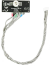
Are the pins for the LED module documented somewhere? IF you go by the color of the insulation, then red, green and blue would be the LED inputs. The black would be ground but, that leaves the gray wire without a color code. I'm sure Yuneec wouldn't have made it that easy.
Attachments
See this thread
Post in thread 'Typhoon H binding problem. No orange lights'
Typhoon H binding problem. No orange lights
Post in thread 'Typhoon H binding problem. No orange lights'
Typhoon H binding problem. No orange lights
Wow! Thank you!See this thread
Post in thread 'Typhoon H binding problem. No orange lights'
Typhoon H binding problem. No orange lights
The LED module appears to marked correctly.
- Blue - Blue LED control
- Red - Red LED control
- Green - Green LED control
- Black - Ground
- unmarked - VBAT
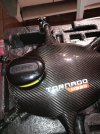
Salve questa è una modifica fatta sul Yuneec Tornado H 920 vola alla grande ,con centralina Naza ,uso la st 24 come monito scatta foto e video , gimbal gb 603 e lumix gh 3 ,e con il telecomando fly sky lo guido tramite interruttore aziono gps , rth, manuale ,e uno aziono i carrelli retrattili , ma ho un problema con il movimento del gimbal...seguono altre foto.
Attachments
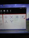
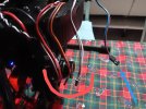
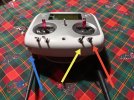
Il gimbal si associa ,come potete vedere la freccia Azzurra sul telecomando c'e un potenziometro una a dx uno a sx che vorrei adoperare per l'inclinazione e uno per la rotazione della cam ,ma non so come inserire i tre fili evidenziati con il Rosso , mentre il filo con la freccia Azzurra che collego alla ricevente aziona i carrelli ......riguardo hai fili menzionati con il rosso sapete dirmi qualcosa?come collegamento.Grazie


