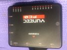
Not sure I understand your question. The wires shown in the photo are connected to the JR plugs that are plugged into the FCØ. Number 1 goes to M1 on the FCØ, etc etc. These wires then let the FCØ control the electronic speed control ( ESC) which then control the motors. I am not sure which arm is controlled by M1. If you can connect to the GUI, each motor can be verified by actuating them individually from the GUI diagram.