Hello Fellow Yuneec Pilot!
Join our free Yuneec community and remove this annoying banner!
Sign up

CGO2, CGO3, CGO3+ boards

Joined
Mar 4, 2019
Messages
400
Reaction score
210
Age
55
I have a question I am hoping some of the smarter drone pilots on here can help me with.

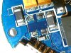
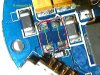
I have a CGO2 board I am playing around with and a CGO3+ board I am studying. I don't plan to make any repairs myself but I only want the information so I can better understand these toys of ours.

On my CGO3+ gimbal board, there is a common mode choke that is soldered between the - and + sides. It is a surface mount choke but has no markings on it. The one on the CGO2 board also has no markings. I have searched all day and cannot find the schematics for anything Yuneec makes. I am starting to wonder why the secrecy from Yuneec. Most electronics manufacturers have their schematics for their customers to use. Anyway.....

Take a look at these pictures and tell me what you guys think. I need the resistance of the common mode choke so I can get a new one and send it off to have it soldered on. Any info would be great.WIN_20200519_12_23_51_Pro.jpg
 

Attachments

  • WIN_20200519_12_26_14_Pro.jpg
    WIN_20200519_12_26_14_Pro.jpg
    106.7 KB · Views: 35
  • WIN_20200517_22_21_41_Pro.jpg
    WIN_20200517_22_21_41_Pro.jpg
    32.3 KB · Views: 38
  • WIN_20200519_12_26_14_Pro.jpg
    WIN_20200519_12_26_14_Pro.jpg
    137.8 KB · Views: 36
  • Like
Reactions: Yuneec Skins
Since it is a choke you will not be able to get a resistance measurement. An ohmmeter will just see a short. The actual measurement would be inductance which is measured in Henries. From the photos of the burned up part it appears that there were two winds per coil.

If the one that is intact is the same physical size it is likely they are of the same values.

Working as a maintenance electrician and electronic tech for years I have seen many instances of schematics only being available for a company’s own technicians. This is to keep actual designs secret. Along with that, components will be defaced or have special markings for that particular company.

As a customer it truly chafes me for a company to do that, but as a tech I understand why it is done.
 
available for a company’s own technicians.
Yeah, I figured it was a secrecy type issue since Yuneec and DJI were doing battle. I think that thing is a DM choke for DC signals? I am guessing the values should be really low since it only has a couple of windings to it. I have been looking for a replacement with TDK or Wurth and not the cheaper Chinese version this one is.
Thanks for your insight. I am truly lost when it comes to stuff like this but I completely LOVE the challenge. Would you be able to tell me what values would be safe to use with these boards?
 
If the one that is intact is the same physical size it is likely they are of the same values.
The choke pictured came from a CGO2 board. I removed it to see how it was soldered into the board. Correct me if I am wrong but doesn't the loose copper wiring have to be soldered under each post? In a crisis cross-type action or would it only have two points that it connects? It is truly hard to see where the wires went.

Is this used to reduce the frequency of the 5.8ghz wifi signals or voltage interference (noise) from the drone battery?
 
A choke is placed inline with a DC source to inhibit AC signals from mixing into the circuit. So if there are two coils in the common mode choke one coil is + to + and the other is - to -.

This site has some good reading on the subject Common Mode Choke | Coilcraft.

Can you ohm out the one from the CGO2 to know which terminals are connected to each other? Does that match with the circuitry so the coils conduct + to + and - to -?
I am working with a tech with Mouser Electronics on a part. He is asking for the working amps of the gimbal/camera. Any ideas? I wouldn't think this thing would be more than 2 or 3 amps. I know the drone itself is around 30 amps.
 
Last edited:
@WTFDproject might have a better idea of the amperage used in those circuits. You are probably correct in your assumption. Physical size and form factor will get you in the ballpark anyway. The K fuse in the aircraft that feeds the camera and gimbal is 1.5A.
 
Depends on the input voltage. Measured on a fully charged TH Battery, with camera bound and broadcasting WiFi, current ranged from about 300 to 400 milliamps. Measured on a steady grip (9.9v measured), it was ranging from about 500 to 700 milliamps. Bottom of range is holding camera steady, top of range is moving the gimbal around a lot. Got about the same readings on two cameras. Could not get manual tilt or yaw to work with the ammeter in the circuit.
I'm guessing 1000 milliamps (1AMP) is a pretty decent assumption for working current.
Sounds good to me. This is the info I have needed. Thank you both for the help. I tried contacting Yuneec engineers with no luck.

If you don't mind, take a look at this choke and tell me if you think it is fairly safe to use.

or this one
 
Either of these would likely suffice as long as the package dimensions match the board layout.

As a way to check if there is anything else wrong with this board before going to the trouble of ordering a part and soldering it in place, you could solder jumper wires to the board. This would allow you to give a quick test to see if something downstream caused the failure of the choke. I would suggest placing a 1.5 A fuse inline for the supply to the camera to save cooking anything else on the board while testing.
 
  • Like
Reactions: cabinfourus
Either of these would likely suffice as long as the package dimensions match the board layout.

As a way to check if there is anything else wrong with this board before going to the trouble of ordering a part and soldering it in place, you could solder jumper wires to the board. This would allow you to give a quick test to see if something downstream caused the failure of the choke. I would suggest placing a 1.5 A fuse inline for the supply to the camera to save cooking anything else on the board while testing.
I wondered if that was possible. I will try that and go from there. I looked the board over pretty good with my digital microscope and didn't see anything else. It was involved in a crash and I am thinking it was jarred loose somehow. It was still partially attached but two legs were loose. Thanks for all the great advice. It seems we the dedicated Yuneec pilots must stick together when it comes to our repairs, we can't count on Yuneec nowadays.
 
Since it is a choke you will not be able to get a resistance measurement. An ohmmeter will just see a short. The actual measurement would be inductance which is measured in Henries. From the photos of the burned up part it appears that there were two winds per coil.

If the one that is intact is the same physical size it is likely they are of the same values.

Working as a maintenance electrician and electronic tech for years I have seen many instances of schematics only being available for a company’s own technicians. This is to keep actual designs secret. Along with that, components will be defaced or have special markings for that particular company.

As a customer it truly chafes me for a company to do that, but as a tech I understand why it is done.
Why dont I kno about Henries? Im taking my bachelors degree back to the tech school i got it from. Maybe I was absent that day or just assumed inductance was an ampere measurement. Anyway inductance usually leads to a jump up or down in voltage and sometimes a change in direction (ie ac to dc) so be carefull with those Lipos. Ive never ignighted one but i once slightly dented one and got a heck of a chemical/electrical burn
 
Why dont I kno about Henries? Im taking my bachelors degree back to the tech school i got it from. Maybe I was absent that day or just assumed inductance was an ampere measurement. Anyway inductance usually leads to a jump up or down in voltage and sometimes a change in direction (ie ac to dc) so be carefull with those Lipos. Ive never ignighted one but i once slightly dented one and got a heck of a chemical/electrical burn
Jump up or down in voltage is with AC circuits in transformers. Two coils (inductors) are placed where their magnetic fields interact. If both have the same number of windings, the voltage across them stays the same and it is termed an isolation transformer. When the windings differ you get a step up or step down transformer.

The use of the coil in the camera circuit above is as a choke. A choke resists the flow of AC in a circuit while DC passes easily. It filters out AC noise in the circuit. Choke and filter are used synonymously.
 
  • Like
Reactions: NorWiscPilot
Jump up or down in voltage is with AC circuits in transformers. Two coils (inductors) are placed where their magnetic fields interact. If both have the same number of windings, the voltage across them stays the same and it is termed an isolation transformer. When the windings differ you get a step up or step down transformer.

The use of the coil in the camera circuit above is as a choke. A choke resists the flow of AC in a circuit while DC passes easily. It filters out AC noise in the circuit. Choke and filter are used synonymously.
Thanks for that bit o knowledge
 
A choke is placed inline with a DC source to inhibit AC signals from mixing into the circuit. So if there are two coils in the common mode choke one coil is + to + and the other is - to -.

This site has some good reading on the subject Common Mode Choke | Coilcraft.

Can you ohm out the one from the CGO2 to know which terminals are connected to each other? Does that match with the circuitry so the coils conduct + to + and - to -?
It has been a long time since I have been able to update my posts. I did have an old cgo2 board lying around and I stole a choke from it. After reflowing the choke to the cgo3+ board, I now have a working camera gimbal. I didn't try to solder it since it was so small. I used solder paste on the four corners and used hot air to seat it. Worked like a champ!
 

New Posts

Members online

Forum statistics

Threads
20,955
Messages
241,587
Members
27,284
Latest member
csandoval