

- Joined
- Mar 23, 2016
- Messages
- 2,401
- Reaction score
- 2,164
- Location
- Bavaria / Germany
- Website
- h-elsner.mooo.com
I'm trying to use the CGO3+ with a H920. Tilt was not possible with the PWM signal from H920 flight controller. CGO3+ is only working with H920+.
The idea is now to take the channel data from SR24 and control the CGO3+. As first step it works for the CGO3+.
Now I have a camera that can be used with ST16 alone.
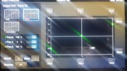
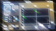
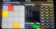
This is enough to control pan, tilt, pan mode and tilt mode:

You can set the camera on the roof top and look around") .
.
Next step will be to manipulate the other channels and send it through to the H920 flight controller. Coming soon.
The idea is now to take the channel data from SR24 and control the CGO3+. As first step it works for the CGO3+.
Now I have a camera that can be used with ST16 alone.
This is enough to control pan, tilt, pan mode and tilt mode:
You can set the camera on the roof top and look around
.
Code:
/*
This device acts as controller for the CGO3+ with SR24 and ST16.
The processor reads the channel data from ST16 and send following
data via control message to CGO3+:
- pan
- tilt
- pan mode
- tilt mode.
Camera settings and video stream still using WiFi connection.

You need power source for the camera 12-16V (VBAT, GND) and a step-down converter to 3.3V for the ESP32.
3.3V for SR24 comes from ESP32 board.
CGO3_TXD2 to cam mRx/PWM
CGO3_RXD2 to cam mTx
Wiring depends on HW port definition below.
*/

#define BINDPIN 14
#define SR24_RXD1 19      // serial1 SR24  yellow
#define SR24_TXD1 18      // gray          GND black, 3.3v white
#define CGO3_RXD2 16      // mTx
#define CGO3_TXD2 17      // mRx/PWM

#define UART_speed 115200
#define X25_INIT_CRC 0xFFFF
#define CRC_EXTRA 0
#define sr24header 0x55

const byte BINDARR[11] = {0x55, 0x55, 0x08, 0x04, 0x00, 0x00, 0x42, 0x49, 0x4E, 0x44, 0xB0};
//                        hd1   hd2   len     1    2      3    4     5      6    7    CRC (for payload 0..7 = 8 bytes)
//                                    SR24buffer

byte sr24buffer[44];

//                                                                         pan------ tilt-----       pan mode- tilt mode          CRC_l CRC_h
byte cgo3buffer[36] = {0xFE,26,0,1,0,2,0,1,0,0,0,0,0,0,0,0,0,0,0x37,0,8,0, 0x00,0x08,0xAB,0x02, 0,8, 0xAB,0x02,0x88,0x08, 0xF4,1, 0x00, 0x00};
byte cgo3sequno = 1;

static inline void crc_accumulate(uint8_t data, uint16_t *crcAccum) {
  // Accumulate one byte of data into the CRC
    uint8_t tmp;
    tmp = data ^ (uint8_t)(*crcAccum &0xFF);
    tmp ^= (tmp<<4);
    *crcAccum = (*crcAccum>>8) ^ (tmp<<8) ^ (tmp <<3) ^ (tmp>>4);
}

void setup() {
  btStop();

  Serial.begin(UART_speed);
  Serial1.begin(UART_speed, SERIAL_8N1, SR24_RXD1, SR24_TXD1);       // SR24
  Serial2.begin(UART_speed, SERIAL_8N1, CGO3_RXD2, CGO3_TXD2);       // Camera

// Set the receiver into bind mode during boot by button on GPIO14
  pinMode(BINDPIN, INPUT_PULLUP);
    delay(100);
  if (digitalRead(BINDPIN) == LOW) {
    delay(500);
    Serial1.write(BINDARR, 11);
    delay(200);
    Serial1.write(BINDARR, 11);
 }

}

void loop() {
  uint16_t crc16;
  uint16_t aux;
  byte incomingByte = 0;
  byte sr24len = 0;
  byte numreadbytes = 0;

  if (Serial1.available() > 0) {
    incomingByte = Serial1.read();
    if ((incomingByte == sr24header) && (Serial1.peek() == sr24header)) {

/*
SR24 like message header found. Header 1 and 2 = 0x55
We peek the length of the message and load the whole message in the sr24buffer.
Buffer contains the message inclucsive msg length and CRC8, but not the 2 header bytes.

If not we send simply the received byte.
*/
      incomingByte = Serial1.read();     // header2
      sr24len = Serial1.peek();          // Msg length
      numreadbytes = Serial1.readBytes(sr24buffer, sr24len+1);

      if (numreadbytes == sr24len+1) {
/*
Complete message received (buffer read matches msg length). Now we need to check
the message type in sr24buffer[1]. Channel messages can be used to create a
control message for a Yuneec camera (here the CGO3+).

If messaage is broken the buffer will send anyway.
*/
        if ((sr24buffer[1] == 0) || (sr24buffer[1] == 1) || (sr24buffer[1] == 3)) {
/*
Create a control message for CGO3+ with default values in unused parameters.
Pan, tilt, pan mode, and tilt mode will be taken from SR24 message and overwritten in
CGO3+ default message.
After that the CRC16 will be recreated and the message will be sent to CGO3+ port.
CRC16 calculation from https://github.com/mavlink/c_library_v2/blob/master/checksum.h
*/
          cgo3sequno++;
          cgo3buffer[2] = cgo3sequno;

          cgo3buffer[22] = sr24buffer[17];                            // Camera pan
          cgo3buffer[23] = (sr24buffer[16] & 0x0F);

          aux = (sr24buffer[15] << 4) + (sr24buffer[16] >> 4);        // Camera  tilt
          Serial.println("Tilt="+String(aux));

          cgo3buffer[24] = lowByte(aux);
          cgo3buffer[25] = highByte(aux);

          cgo3buffer[28] = sr24buffer[20];                            // Pan mode
          cgo3buffer[29] = sr24buffer[19] & 0x0F;

          aux = (sr24buffer[18] << 4) + (sr24buffer[19] >> 4);        // Camera  tilt mode
          cgo3buffer[30] = lowByte(aux);
          cgo3buffer[31] = highByte(aux);

          crc16 = 0xFFFF;
          for (uint8_t k=1; k<34; k=k+1) {
            crc_accumulate(cgo3buffer[k], &crc16);
          }
          crc_accumulate(CRC_EXTRA, &crc16);
          cgo3buffer[34] = lowByte(crc16);
          cgo3buffer[35] = highByte(crc16);

          Serial2.write(cgo3buffer, 36);                                 //  To CGO3+
        }

      }

    }

  }

}
Next step will be to manipulate the other channels and send it through to the H920 flight controller. Coming soon.
Last edited:


")