Hello Fellow Yuneec Pilot!
Join our free Yuneec community and remove this annoying banner!
Sign up

CGO3+ with ST16 but without drone

h-elsner

Premium Pilot
Joined
Mar 23, 2016
Messages
2,363
Reaction score
2,103
Location
Bavaria / Germany
Website
h-elsner.mooo.com
I'm trying to use the CGO3+ with a H920. Tilt was not possible with the PWM signal from H920 flight controller. CGO3+ is only working with H920+.

The idea is now to take the channel data from SR24 and control the CGO3+. As first step it works for the CGO3+.
Now I have a camera that can be used with ST16 alone.
This is enough to control pan, tilt, pan mode and tilt mode:
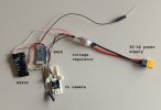
CGO3P_ESP32.jpg

You can set the camera on the roof top and look around :).

Code:
/*
This device acts as controller for the CGO3+ with SR24 and ST16.
The processor reads the channel data from ST16 and send following
data via control message to CGO3+:
- pan
- tilt
- pan mode
- tilt mode.
Camera settings and video stream still using WiFi connection.

You need power source for the camera 12-16V (VBAT, GND) and a step-down converter to 3.3V for the ESP32.
3.3V for SR24 comes from ESP32 board.
CGO3_TXD2 to cam mRx/PWM
CGO3_RXD2 to cam mTx
Wiring depends on HW port definition below.
*/

#define BINDPIN 14
#define SR24_RXD1 19      // serial1 SR24  yellow
#define SR24_TXD1 18      // gray          GND black, 3.3v white
#define CGO3_RXD2 16      // mTx
#define CGO3_TXD2 17      // mRx/PWM

#define UART_speed 115200
#define X25_INIT_CRC 0xFFFF
#define CRC_EXTRA 0
#define sr24header 0x55

const byte BINDARR[11] = {0x55, 0x55, 0x08, 0x04, 0x00, 0x00, 0x42, 0x49, 0x4E, 0x44, 0xB0};
//                        hd1   hd2   len     1    2      3    4     5      6    7    CRC (for payload 0..7 = 8 bytes)
//                                    SR24buffer

byte sr24buffer[44];

//                                                                         pan------ tilt-----       pan mode- tilt mode          CRC_l CRC_h
byte cgo3buffer[36] = {0xFE,26,0,1,0,2,0,1,0,0,0,0,0,0,0,0,0,0,0x37,0,8,0, 0x00,0x08,0xAB,0x02, 0,8, 0xAB,0x02,0x88,0x08, 0xF4,1, 0x00, 0x00};
byte cgo3sequno = 1;

static inline void crc_accumulate(uint8_t data, uint16_t *crcAccum) {
  // Accumulate one byte of data into the CRC
    uint8_t tmp;
    tmp = data ^ (uint8_t)(*crcAccum &0xFF);
    tmp ^= (tmp<<4);
    *crcAccum = (*crcAccum>>8) ^ (tmp<<8) ^ (tmp <<3) ^ (tmp>>4);
}

void setup() {
  btStop();

  Serial.begin(UART_speed);
  Serial1.begin(UART_speed, SERIAL_8N1, SR24_RXD1, SR24_TXD1);       // SR24
  Serial2.begin(UART_speed, SERIAL_8N1, CGO3_RXD2, CGO3_TXD2);       // Camera
 
// Set the receiver into bind mode during boot by button on GPIO14
  pinMode(BINDPIN, INPUT_PULLUP);
    delay(100);
  if (digitalRead(BINDPIN) == LOW) {
    delay(500);
    Serial1.write(BINDARR, 11);
    delay(200);
    Serial1.write(BINDARR, 11);
 }

}

void loop() {
  uint16_t crc16;
  uint16_t aux;        
  byte incomingByte = 0;
  byte sr24len = 0;
  byte numreadbytes = 0;

  if (Serial1.available() > 0) {
    incomingByte = Serial1.read();
    if ((incomingByte == sr24header) && (Serial1.peek() == sr24header)) {

/*
SR24 like message header found. Header 1 and 2 = 0x55
We peek the length of the message and load the whole message in the sr24buffer.
Buffer contains the message inclucsive msg length and CRC8, but not the 2 header bytes.

If not we send simply the received byte.
*/
      incomingByte = Serial1.read();     // header2
      sr24len = Serial1.peek();          // Msg length
      numreadbytes = Serial1.readBytes(sr24buffer, sr24len+1);

      if (numreadbytes == sr24len+1) {                          
/*
Complete message received (buffer read matches msg length). Now we need to check
the message type in sr24buffer[1]. Channel messages can be used to create a
control message for a Yuneec camera (here the CGO3+).

If messaage is broken the buffer will send anyway.
*/
        if ((sr24buffer[1] == 0) || (sr24buffer[1] == 1) || (sr24buffer[1] == 3)) {
/*
Create a control message for CGO3+ with default values in unused parameters.
Pan, tilt, pan mode, and tilt mode will be taken from SR24 message and overwritten in
CGO3+ default message.
After that the CRC16 will be recreated and the message will be sent to CGO3+ port.
CRC16 calculation from https://github.com/mavlink/c_library_v2/blob/master/checksum.h
*/
          cgo3sequno++;
          cgo3buffer[2] = cgo3sequno;

          cgo3buffer[22] = sr24buffer[17];                            // Camera pan
          cgo3buffer[23] = (sr24buffer[16] & 0x0F);

          aux = (sr24buffer[15] << 4) + (sr24buffer[16] >> 4);        // Camera  tilt
          Serial.println("Tilt="+String(aux));

          cgo3buffer[24] = lowByte(aux);
          cgo3buffer[25] = highByte(aux);
         
          cgo3buffer[28] = sr24buffer[20];                            // Pan mode
          cgo3buffer[29] = sr24buffer[19] & 0x0F;

          aux = (sr24buffer[18] << 4) + (sr24buffer[19] >> 4);        // Camera  tilt mode
          cgo3buffer[30] = lowByte(aux);
          cgo3buffer[31] = highByte(aux);

          crc16 = 0xFFFF;
          for (uint8_t k=1; k<34; k=k+1) {
            crc_accumulate(cgo3buffer[k], &crc16);
          }
          crc_accumulate(CRC_EXTRA, &crc16);
          cgo3buffer[34] = lowByte(crc16);
          cgo3buffer[35] = highByte(crc16);

          Serial2.write(cgo3buffer, 36);                                 //  To CGO3+
        }                                                          

      }

    }

  }

}

Next step will be to manipulate the other channels and send it through to the H920 flight controller. Coming soon.
 
Last edited:
I'm trying to use the CGO3+ with a H920. Tilt was not possible with the PWM signal from H920 flight controller. CGO3+ is only working with H920+.

The idea is now to take the channel data from SR24 and control the CGO3+. As first step it works for the CGO3+.
Now I have a camera that can be used with ST16 alone.
This is enough to control pan, tilt, pan mode and tilt mode:

View attachment 32347

You can set the camera on the roof top and look around :).

Code:
/*
This device acts as controller for the CGO3+ with SR24 and ST16.
The processor reads the channel data from ST16 and send following
data via control message to CGO3+:
- pan
- tilt
- pan mode
- tilt mode.
Camera settings and video stream still using WiFi connection.

You need power source for the camera 12-16V (VBAT, GND) and a step-down converter to 3.3V for the ESP32.
3.3V for SR24 comes from ESP32 board.
CGO3_TXD2 to cam mRx/PWM
CGO3_RXD2 to cam mTx
Wiring depends on HW port definition below.
*/

#define BINDPIN 14
#define SR24_RXD1 19      // serial1 SR24  yellow
#define SR24_TXD1 18      // gray          GND black, 3.3v white
#define CGO3_RXD2 16      // mTx
#define CGO3_TXD2 17      // mRx/PWM

#define UART_speed 115200
#define X25_INIT_CRC 0xFFFF
#define CRC_EXTRA 0
#define sr24header 0x55

const byte BINDARR[11] = {0x55, 0x55, 0x08, 0x04, 0x00, 0x00, 0x42, 0x49, 0x4E, 0x44, 0xB0};
//                        hd1   hd2   len     1    2      3    4     5      6    7    CRC (for payload 0..7 = 8 bytes)
//                                    SR24buffer

byte sr24buffer[44];

//                                                                         pan------ tilt-----       pan mode- tilt mode          CRC_l CRC_h
byte cgo3buffer[36] = {0xFE,26,0,1,0,2,0,1,0,0,0,0,0,0,0,0,0,0,0x37,0,8,0, 0x00,0x08,0xAB,0x02, 0,8, 0xAB,0x02,0x88,0x08, 0xF4,1, 0x00, 0x00};
byte cgo3sequno = 1;

static inline void crc_accumulate(uint8_t data, uint16_t *crcAccum) {
  // Accumulate one byte of data into the CRC
    uint8_t tmp;
    tmp = data ^ (uint8_t)(*crcAccum &0xFF);
    tmp ^= (tmp<<4);
    *crcAccum = (*crcAccum>>8) ^ (tmp<<8) ^ (tmp <<3) ^ (tmp>>4);
}

void setup() {
//  WiFi.mode(WIFI_OFF);
  btStop();

  Serial.begin(UART_speed);
  Serial1.begin(UART_speed, SERIAL_8N1, SR24_RXD1, SR24_TXD1);       // SR24
  Serial2.begin(UART_speed, SERIAL_8N1, CGO3_RXD2, CGO3_TXD2);       // Camera
 
// Set the receiver into bind mode during boot by button on GPIO14
  pinMode(BINDPIN, INPUT_PULLUP);
    delay(100);
  if (digitalRead(BINDPIN) == LOW) {
    delay(500);
    Serial1.write(BINDARR, 11);
    delay(200);
    Serial1.write(BINDARR, 11);
 }

}

void loop() {
  uint16_t crc16;
  uint16_t aux;         
  byte incomingByte = 0;
  byte sr24len = 0;
  byte numreadbytes = 0;

  if (Serial1.available() > 0) {
    incomingByte = Serial1.read();
    if ((incomingByte == sr24header) && (Serial1.peek() == sr24header)) { 

/*
SR24 like message header found. Header 1 and 2 = 0x55
We peek the length of the message and load the whole message in the sr24buffer.
Buffer contains the message inclucsive msg length and CRC8, but not the 2 header bytes.

If not we send simply the received byte.
*/
      incomingByte = Serial1.read();     // header2
      sr24len = Serial1.peek();          // Msg length
      numreadbytes = Serial1.readBytes(sr24buffer, sr24len+1); 

      if (numreadbytes == sr24len+1) {                           
/*
Complete message received (buffer read matches msg length). Now we need to check
the message type in sr24buffer[1]. Channel messages can be used to create a
control message for a Yuneec camera (here the CGO3+).

If messaage is broken the buffer will send anyway.
*/
        if ((sr24buffer[1] == 0) || (sr24buffer[1] == 1) || (sr24buffer[1] == 3)) {
/*
Create a control message for CGO3+ with default values in unused parameters.
Pan, tilt, pan mode, and tilt mode will be taken from SR24 message and overwritten in
CGO3+ default message.
After that the CRC16 will be recreated and the message will be sent to CGO3+ port.
CRC16 calculation from https://github.com/mavlink/c_library_v2/blob/master/checksum.h
*/
          cgo3sequno++;
          cgo3buffer[2] = cgo3sequno;

          cgo3buffer[22] = sr24buffer[17];                            // Camera pan
          cgo3buffer[23] = (sr24buffer[16] & 0x0F);

          aux = (sr24buffer[15] << 4) + (sr24buffer[16] >> 4);        // Camera  tilt
          Serial.println("Tilt="+String(aux));

          cgo3buffer[24] = lowByte(aux);
          cgo3buffer[25] = highByte(aux);
          
          cgo3buffer[28] = sr24buffer[20];                            // Pan mode
          cgo3buffer[29] = sr24buffer[19] & 0x0F;

          aux = (sr24buffer[18] << 4) + (sr24buffer[19] >> 4);        // Camera  tilt mode
          cgo3buffer[30] = lowByte(aux);
          cgo3buffer[31] = highByte(aux);

          crc16 = 0xFFFF;
          for (uint8_t k=1; k<34; k=k+1) {
            crc_accumulate(cgo3buffer[k], &crc16);
          }
          crc_accumulate(CRC_EXTRA, &crc16);
          cgo3buffer[34] = lowByte(crc16);
          cgo3buffer[35] = highByte(crc16);

          Serial2.write(cgo3buffer, 36);                                 //  To CGO3+
        }                                                           

      }

    }

  }

}

Next step will be to manipulate the other channels and send it through to the H920 flight controller. Coming soon.
Huh? I lost you after the 1st sentence but good luck.
 
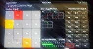
The redundancy channel via WiFi can be redirected to UART. Some external device shoud be used. Without SR24 at all. For 920 redundancy is useless.
 
The redundancy channel can also be used (control the CGO3+ gimbal without SR24 at all - only for ST16):

Code:
/*
This device acts as controller for the CGO3+ ST16.
The processor reads the channel data from ST16 and send following
data via control message to CGO3+:
- pan
- tilt
- pan mode
- tilt mode.
Camera settings and video stream still using WiFi connection.

You need power source for the camera 12-16V (VBAT, GND) and a step-down
converter to 3.3V (or 5V depending on ESP32 module type) for the ESP32.
CGO3_TXD2 to cam mRx/PWM
CGO3_RXD2 to cam mTx
Wiring depends on HW port definition below.
*/

#define LEDlightPIN 22    // LED illumination
#define AUX_PIN 23        // Additional switch contact
#define CGO3_RXD2 16      // mTx
#define CGO3_TXD2 17      // mRx/PWM
#define UART_speed 115200
#define X25_INIT_CRC 0xFFFF
#define cgo3buffer_size 47   // Max number of bytes in incoming message
#define FEheader 0xFE

byte cgo3buffer[cgo3buffer_size];
//                                                                              pan------ tilt-----       pan mode- tilt mode          CRC_l CRC_h
byte cgo3send_buffer[36] = {0xFE,26,0,1,0,2,0,1,0,0,0,0,0,0,0,0,0,0,0x37,0,8,0, 0x00,0x08,0xAB,0x02, 0,8, 0xAB,0x02,0x88,0x08, 0xF4,1, 0x00, 0x00};

static inline void crc_accumulate(uint8_t data, uint16_t *crcAccum) {
  // Accumulate one byte of data into the CRC
  uint8_t tmp;
  tmp = data ^ (uint8_t)(*crcAccum &0xFF);
  tmp ^= (tmp<<4);
  *crcAccum = (*crcAccum>>8) ^ (tmp<<8) ^ (tmp <<3) ^ (tmp>>4);
}

void setup() {
  btStop();
//   Serial.begin(UART_speed);     // Debug
  Serial2.begin(UART_speed, SERIAL_8N1, CGO3_RXD2, CGO3_TXD2);       // Camera
  pinMode(LEDlightPIN, OUTPUT);
  delay(100);
  digitalWrite(LEDlightPIN, LOW);
  pinMode(AUX_PIN, OUTPUT);
  delay(100);
  digitalWrite(AUX_PIN, LOW);
}

void loop() {
  uint16_t crc16;
  uint16_t aux = 0;         
  byte cgo3len = 0;
  byte incomingByte = 0;
  int numreadbytes = 0;
  byte cgo3sequno = 0;
  if (Serial2.available() > 0) {
    incomingByte = Serial2.read();
    cgo3len = Serial2.peek();
    if ((incomingByte == FEheader) && (cgo3len == 38)) {    // Possible a message ChannelData 5GHz.
      numreadbytes = Serial2.readBytes(cgo3buffer, cgo3len+9); 
      if ((numreadbytes == cgo3len+9) &&  (cgo3buffer[2] == 4) && (cgo3buffer[6] == 8)) {   // This SysID and Message ID contains channel data
        cgo3send_buffer[22] = cgo3buffer[37];                            // Camera pan
        cgo3send_buffer[23] = (cgo3buffer[36] & 0x0F);                   // 12 bytes per channel
        aux = (cgo3buffer[35] << 4) + (cgo3buffer[36] >> 4);             // Camera  tilt
        cgo3send_buffer[24] = lowByte(aux);
        cgo3send_buffer[25] = highByte(aux);
        cgo3send_buffer[28] = cgo3buffer[40];                            // Pan mode
        cgo3send_buffer[29] = cgo3buffer[39] & 0x0F;
        aux = (cgo3buffer[38] << 4) + (cgo3buffer[39] >> 4);             // Camera  tilt mode
        cgo3send_buffer[30] = lowByte(aux);
        cgo3send_buffer[31] = highByte(aux);

        aux = (cgo3buffer[41] << 4) + (cgo3buffer[42] >> 4);             // Optional: Switch on/off light with LG switch channel 10
        if (aux > 2048) {
          digitalWrite(LEDlightPIN, HIGH);
        } else {
          digitalWrite(LEDlightPIN, LOW);
        }
        aux = cgo3buffer[42] & 0x0F;                                     // Optional: Switch something else with AUX button
        if (aux < 8) {
          digitalWrite(AUX_PIN, HIGH);
        } else {
          digitalWrite(AUX_PIN, LOW);
        }

        cgo3send_buffer[2] = cgo3sequno;
        crc16 = 0xFFFF;
        for (uint8_t k=1; k<34; k++) {
          crc_accumulate(cgo3send_buffer[k], &crc16);
        }
        crc_accumulate(0, &crc16);
        cgo3send_buffer[34] = lowByte(crc16);
        cgo3send_buffer[35] = highByte(crc16);
        Serial2.write(cgo3send_buffer, 36);             
        cgo3sequno++;
      }                                                       
    }
  }
}
 
You can do some research to add a GPS data in the EXIF, as well to prepare some kind of RTK. Megapixels aren't so much, but possibility to have almost accurate gimbal position in a paired log file will give a new idea about post processing. BTW, this is rebirth of an old idea, privately discussed, which haven't had a place, due to lack of reversed engineering basis.

Data transfer between rover and land on 432 MHz will be a good option. Some development kits are available as second hand after project monetization.
 
As a starter, GPS + IMU board from (if I'm memorized right) Breeze is a good candidate.
For RTK should be used RTK enabled receiver...
 
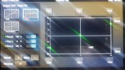
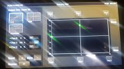
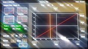
CGO3+ has a pointing pan mode as C23/E90. Should to reproduce the sequence to initialize it and will post here. Soon...
This mode is very useful.
 
SR24 implemented as a controller (remote like ST16/24) on the camera will add a lot of automation for Thunderbird, 920 etc.

The description of SR24 UART protocol in an ST16 was in your old private messages. It isn't fully the same as in the drone.
 
CGO3+ has a pointing pan mode as C23/E90. Should to reproduce the sequence to initialize it and will post here. Soon...
This mode is very useful.
 

Attachments

  • 20250529_162939.jpg
    20250529_162939.jpg
    627.5 KB · Views: 1
  • 20250529_162825.jpg
    20250529_162825.jpg
    901.7 KB · Views: 1
  • Q_1748525503545.jpg
    Q_1748525503545.jpg
    933.9 KB · Views: 1
  • 20250529_162907.jpg
    20250529_162907.jpg
    933.9 KB · Views: 1
more...
 

Attachments

  • 20250529_165450.jpg
    20250529_165450.jpg
    782.2 KB · Views: 0
  • 20250529_165520.jpg
    20250529_165520.jpg
    1,013.5 KB · Views: 0
  • 20250529_165617.jpg
    20250529_165617.jpg
    754.2 KB · Views: 0
  • 20250529_165548.jpg
    20250529_165548.jpg
    777.6 KB · Views: 0

New Posts

Members online

No members online now.

Forum statistics

Threads
21,368
Messages
246,106
Members
28,340
Latest member
JimD