Hello Fellow Yuneec Pilot!
Join our free Yuneec community and remove this annoying banner!
Sign up

IMU issue

Joined
Jan 6, 2019
Messages
2
Reaction score
0
Age
35
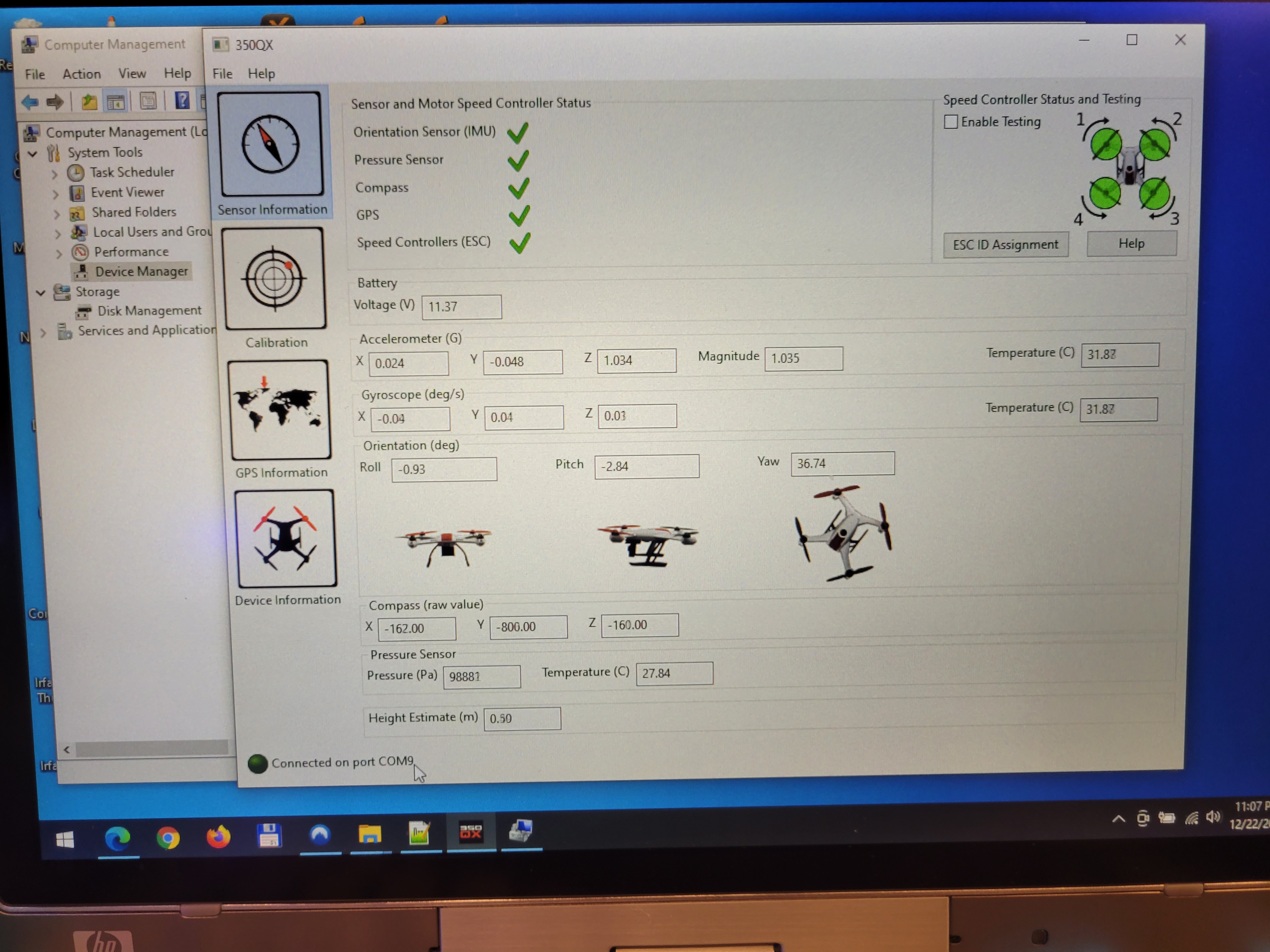
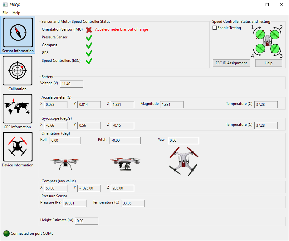
New to the drone world. Bought a secondhand Q500 4K from my brother. I flew it with him a couple months ago and it worked fine. I fired it up yesterday, and it would not connect to the ST-10. The main LED flashes red, 3x per sec. There is also a tone that it makes. I tried to bind everything together. I can get connection to the camera, but not the drone. I got all the GUI software download and hooked up today. The "Orientarion Sensor (IMU)"- accelerometer bias out of range. I tried to recalibrate the accelerometer and the calibration failed from timing out. Is there anything else I can try? Thank you.
 
[QUOTE The "Orientarion Sensor (IMU)"- accelerometer bias out of range. I tried to recalibrate the accelerometer and the calibration failed from timing out. Is there anything else I can try? [/QUOTE]

Unfortunately, the answer for most folks is pretty much "No". IF you are very good with micro soldering, then it can sometimes be fixed. The problem is either the IMU chip itself is bad, or the solder is cracked. These chips look like normal SMD chips when you look at them, but they don't have "legs". The contact points are cut off at the edge of the chip, making it a common solder failure.
Not sure about replacing the chip itself. I have had nearly 100% success when replacing the chip with a salvaged chip from another board. Have had zero success when replacing with a new chip. I'm not an electronics guy, but I suspect the chips have to be programmed before they will work.

First thing I would try would be to carefully re-melt the existing solder around the chip. Not likely to help, but it might.
Replacing the chip from a salvage board requires the use of a Hot Air rework station, and some experience.

The most reliable fix is to replace the entire mainboard, which requires some soldering skill, but within the range of the average
DIY person.

The chip is circled in white in this drawing:
Board Post.jpg
 
Thank you for your reply. I'm not so confident in small electronics. I will look at it and see if there is anything visual. I appreciate the picture as well. Thanks again.
 
I got a 350 QX that has this exact same problem and am trying to fix it.

I see in the WTFD the IMU for a Q500 is listed as MPU-6050. The board in the QX I have seems quite similar yet not exactly the same. I can't read anything off that IC marking - this QX is quite old and in a rough shape.

Is the QX using the same MPU-6050 IC?

 
Not sure about replacing the chip itself. I have had nearly 100% success when replacing the chip with a salvaged chip from another board. Have had zero success when replacing with a new chip. I'm not an electronics guy, but I suspect the chips have to be programmed before they will work.

I tried and for me it worked. In my previous post I posted the GUI before the fix and below is after replacing it. Also the startup error tone sequence is now gone.The IC is tricky indeed. I do not have a soldering station which made it a nightmare.

In case anyone wants to try it - what worked for me is buying a DIY EVK board for the MPU-6050 from Amazon ($8 .. $10) and getting the IC off of it. you need to get the faulty one off the main board without damaging the board, then get the new MPU off the EVK without destroying it, even out the solder on all "pins" and PCB pads and then solder it. I did it two times on the same board, so it is doable.

Now the lessons learnt:
* Make sure to buy a MPU-5060 EVK board or DIY module that you can clearly see the IC marking on the photo of the item you are buying. The first one I got was with a newer IC that is reverse compatible. (So perfectly compatible that it did not work at all :) )
* Take photos of the chip you are removing. You will need these to orient the new chip when soldering it. There is a big dot next to pin #1
* Find the best camera you have in the house and use it to zoom in and verify you soldered it right. My phone camera did the job perfectly and I found and fixed a crack like the one WTFD described.

So at the end here is the now happy GUI:
 
  • Like
Reactions: DoomMeister
I tried and for me it worked. In my previous post I posted the GUI before the fix and below is after replacing it. Also the startup error tone sequence is now gone.The IC is tricky indeed. I do not have a soldering station which made it a nightmare.

In case anyone wants to try it - what worked for me is buying a DIY EVK board for the MPU-6050 from Amazon ($8 .. $10) and getting the IC off of it. you need to get the faulty one off the main board without damaging the board, then get the new MPU off the EVK without destroying it, even out the solder on all "pins" and PCB pads and then solder it. I did it two times on the same board, so it is doable.

Now the lessons learnt:
* Make sure to buy a MPU-5060 EVK board or DIY module that you can clearly see the IC marking on the photo of the item you are buying. The first one I got was with a newer IC that is reverse compatible. (So perfectly compatible that it did not work at all :) )
* Take photos of the chip you are removing. You will need these to orient the new chip when soldering it. There is a big dot next to pin #1
* Find the best camera you have in the house and use it to zoom in and verify you soldered it right. My phone camera did the job perfectly and I found and fixed a crack like the one WTFD described.

So at the end here is the now happy GUI:
I just got a q500 and was trying to set it up and am having this issue. I can't believe you posted here like an hour before I started researching it, that's some crazy timing! Would you happen to have a link to where you bought a compatible MPU-6050?

Thanks!
 
I just got a q500 and was trying to set it up and am having this issue. I can't believe you posted here like an hour before I started researching it, that's some crazy timing! Would you happen to have a link to where you bought a compatible MPU-6050?

Thanks!

I don't think it is a coincidence. It must have been the Christmas miracle of free time :)

The one that worked was from Amazon:
AEDIKO 2pcs MPU6050 MPU-6050 GY-521 3 Axis Accelerometer Gyroscope Module for Arduino

Before you order check what is the accelerometer on your Q500. There are QX3s with a different IC. Below is another forum's thread with a photo of a MPU-4050 on a newer version of QX3:
Blade 350qx with st10

I have zero idea what Yuneec might have put on yours so make sure what you order an IC with the same markings on it. If in doubt put a photo with a readable marking of the IC here.
A Christmas miracle indeed :)

I just got around to disassembling it, here are some photos of the chip in question.
_DSC0165.jpg

_DSC0165-Edit.jpg
_DSC0174-2.jpg
_DSC0174.jpg
_DSC0181.jpg

My eyes aren't the sharpest but none of the joints immediately looked bad to me.
 
What is this black stuff near the IMU?

It's no clear visible but Pin23 (SCL) soldering looks not good. SCL is clock of the i2c connection between IMU and processor.
View attachment 27417

br HE
I'm pretty sure the black stuff is just permanent marker. I have a friend from college who's good at soldering coming by in a couple weeks, he said this sort of thing should be easy for him.
 

New Posts

Members online

Forum statistics

Threads
20,973
Messages
241,800
Members
27,361
Latest member
Jwclarc1