Hello Fellow Yuneec Pilot!
Join our free Yuneec community and remove this annoying banner!
Sign up

Reverse engineering CGO3+ UART

I'm working on a SW tool to bring the communication between SR24 - drone - gimbal together. I'm using a 4 channel logic analyzer from Saleae and its analyzer SW (luckily available for LINUX too).
Currently no new results but a lot of data will be recorded.
To analyze all the recorded data is a lot of work and any help would be appreciated.
What sort of help? It took a minute but I managed to get the software working on Rocky Linux 9.
 
I'm working on a SW tool to bring the communication between SR24 - drone - gimbal together. I'm using a 4 channel logic analyzer from Saleae and its analyzer SW (luckily available for LINUX too).
Currently no new results but a lot of data will be recorded.
To analyze all the recorded data is a lot of work and any help would be appreciated.
Useful for the community will be If you grab the data to and from SR24 in the ST16. The speed, as I remember, is 230 400. Check out private conversations about three years ago. I wrote all known by me about this part of communication. Of course, not well documented. East provinces EU citizen says everything. Good explained protocol how to use SR24 as a remote will give chance to use DIY controllers.
 
And a bit more. A logic analyser is not necessary here. The communication is pure RS232 everywhere, so a few com ports and hex terminal software is enough. If you want to sync Rx and Tx datagrams should do some tricks. Terminal time stamps will not work correctly. SR24 can transmit and receive simultaneously but probably not chaotic.
 
The basics are pretty clear. ST16 sends Channel data messages (Msg_type 0, 1 or 3) up to drone and receives Telemetry messages (Msg_type 2). Bind message is Msg_type 4. All those are well documented and are enough to use STxx for other projects.

The tricky part is Msg_type 20. Those are H480 specific. Some are clear, some not. Surprisingly I see no messages when I start calibration, also GPS switch looks strange. Here we need to dive deeper.

For feature "Dual Band Control Redundancy" we have to send Channel data via WiFi (and then camera UART) and get back Telemetry. Channel data are pretty clear (Msg_ID=8). I'm looking for telemetry - I think Msg_ID=2 is it but the format needs to be verified. In this case the combination from SR24 and Cam messages may help. Work is ongoing...

Here as example a recording from startup: ST16 off -> ST16 connects -> later WiFi connects -> end of recording.

Edit: Attachment updated (bug fixes)
 
Last edited:
  • Like
Reactions: 1midniterider
As usually, I talked about another thing. Doesn't matter...
Good luck!
 
I have been having a difficult time trying to gain UART control of my CGO3+ movements. I ran across the following about using PWM. Have you tested pwm control?

 
I didn't test this by myself. All those information about the start impulse that is needed (or not) comes from CGO2 and CGO3. If the CGO3+ needs the start pulse we don't know. The easiest way is to test this.
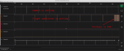
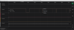
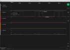
Here is what I have seen on the CGO3+ regarding fallback to PWM.
failed_conn-PWM.pngPWM.pngPWM_cam_horizontal.pngPWM_cam_vertical_down.png
 
The fallback is automatically initiated by flight controller when serial connection fails. I don't know what camera makes when PWM is coming imedially.
As said above, I don't know if the init puls is needed for CGO3+. The communication is different compared to CGO3.
 
My tool to analyze the UART communication between SR24 - FC and FC - camera is more mature now. You can find it here:
The repo includes some testfiles and the documentation what is known up to now.

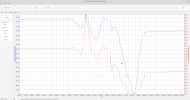
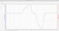
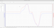
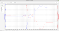
What I want to figure out is the meaning of the of the first 7 16bit values. The control commands to the camera are clear and exact what @Vaklin said above.
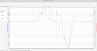
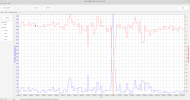
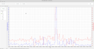
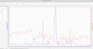
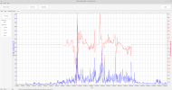
I have compared the message that I called "Attitude" Msg_ID=1 with the telemetry data sent by FC to ST16 (MsgType=2): pitch, roll, yaw, Vx, Vy, Vz.
I have read the 16bit (2 Bytes) words as Int16 all other formats like Float makes no sense. The first two bytes starting on position 8 have no direct relation to any values in the telemetry. Blue are the values in question, red are compared values from telemetry.


Attitude8_pitch.pngAttitude8_yaw.pngAttitude8_roll.png

But the next 2byte starting on position 10 meets perfectly the pitch values from telemetry.
Attitude10_pitch.png

The next 2 bytes (position 12) are somehow near the pitch value. What for?

Attitude12_nearPitch.png

The 2 bytes on position 14 follow Yaw but inverted.
Attitude14_yaw.png

The next two byte corresponding somehow with Vx, Vy and Vz. That's why I think it represents the velocity of the drone.
Attitude16_vx.pngAttitude16_vy.pngAttitude16_vz.png

The following 4 bytes have no relation to anything in the telemetry. Any ideas?
Attitude18_20_no_relation.png
 
Is the CGO3+ init sequence buried in the comms capture you posted?
Yes, in the first picture. Both, FC and camera send heartbeat messages but for some reason the connection was not established. After ~8sec the FC decides to switch to PWM as backwards compatibility. Thus, the old CGO3 can work with H480.
To view this content we will need your consent to set third party cookies.
For more detailed information, see our cookies page.
 
Camera positions... I hope... Check the values in the EXIF in a test picture. BTW this is very important information if it is available on the ground during flight time.
 
Init is possible without waiting. Get the patern from a steady grip.
 
Found it in one old (useless) conversation.

1. Set PWM clock to 5 ms;
2. Power the device (12 volts!);
3. Wait 1.2 seconds;
4. Start PWM init phase with the following sequence -> 40 times (8 times 0.65 ms on in a cycle, 8 times 1.23 ms on in a cycle). The total duration is 3.2 seconds. After that the gimbal is initialized;
4. Fixed position holds with 1 ms high in the cycle, the variable is between 1.1 and 1.85 ms in the cycle.
 
What happens if RC lost:

Switches off ST16 but SR24 still sends Messages 0 and 3 but package counter begins to count from1 to FF (5s) and remains at FF. Messages have the values last sent by the RC although RC was switched off (forever I think, at least until I switches off the machine). FC still sends Message 3 (Telemetry) and message 20 (Additional data, action type 1 (till 9s), 3 and 8 from FC) for next 13s. Then FC stops sending anything.

11.5429178333 package counter starts to count. FC works as usual, sends message 3 and 20
13.5323969166 package counter reaches 100
16.6472205833 package counter reaches 255
24.5301494166 last message 2
24.3336494166 last message 20, msg 0 and 3 still coming from an not existing RC - strange
29.1869264166 switched off all
This was the same behavior I noticed and there is a note in the rc input file in the Thunderbird code about that as well.
 
  • Like
Reactions: h-elsner
Found it in one old (useless) conversation.

1. Set PWM clock to 5 ms;
2. Power the device (12 volts!);
3. Wait 1.2 seconds;
4. Start PWM init phase with the following sequence -> 40 times (8 times 0.65 ms on in a cycle, 8 times 1.23 ms on in a cycle). The total duration is 3.2 seconds. After that the gimbal is initialized;
4. Fixed position holds with 1 ms high in the cycle, the variable is between 1.1 and 1.85 ms in the cycle.
Something like this:

Initializing CGO3 with a servo tester

Code:
int a = 0;
int s = 25;
int z = 0;

void setup() {
  pinMode(13, OUTPUT);
  pinMode(12, OUTPUT);


  analogWrite(11, 0);

  for (int i = 0; i <= 1000; i++) {
    digitalWrite(12, HIGH);
    delay(1);
    digitalWrite(12, LOW);
    delay(4);
  }
  digitalWrite(13, HIGH);
  for (int i = 0; i <= 100; i++) {
    digitalWrite(12, HIGH);
    a = a + s;
    if (a == 0 || a == 1000) {
      s = -s;
    }
    delayMicroseconds(a);
    digitalWrite(12, LOW);
    z = 10000 - a;
    delayMicroseconds(z);
    delay(10);
  }
  digitalWrite(13, LOW);
}

void loop() {
  digitalWrite(12, HIGH);
  delayMicroseconds(1500);
  digitalWrite(12, LOW);
  delayMicroseconds(8500);
  delay(10);
}


Write your reply...

New Posts

Members online

Forum statistics

Threads
21,306
Messages
245,431
Members
28,231
Latest member
heavenlyhimalayan