Hello Fellow Yuneec Pilot!
Join our free Yuneec community and remove this annoying banner!
Sign up

Reverse engineering CGO3+ UART

Question... Should the CGO3+ transmit data before being initialized? I basically wrote a double while loop to capture any output from the CGO3+ UART before being sent the init sequence and it surprised me by actually capturing data on startup.
 
Last edited:
Looks like more than heartbeat, unless it is an erratic one:

Code:
06:52:58.664 -> FF 9F FC 5F FF 9F 35 ED FF 1F FF 9F BF DF EF 77 1F EF 77
06:53:06.615 -> FE FF DF EF BF 9F FF 9F 6F
06:53:09.636 -> FE BF 1F EF FF 6F 1F 6F 9F DF FB FD FC F5 FF 1F BF DF EF AF D5 DF EF 3F AB FF FA DD EF FD
06:53:16.136 -> FE 3F 5D
06:53:16.136 -> FE FF FD
06:53:16.136 -> FE D5 EF F5 DF 3F 57 47 57 D5 FF FF FF 9B FF
06:53:16.168 -> FE DF 67 F7 FB FD FF DF EF F7 FB FD
06:53:16.168 -> FE FF FF DF EF F7 FB FD
06:53:16.168 -> FE DD EF
06:53:16.168 -> FE 1F 6F FD FC D7 FF FA DF ED F5 FB FD AA DF
06:53:17.133 -> FE B7 55 EF 9D AF B5 DF C7 F5 FB 5D FC 3D 5D 4D 75 5B 75 5A FF FF FC DF E7 FF FF FF FF DF EF F7 FB FD
06:53:17.197 -> FE BF DF EF F7 FB FD
06:53:17.197 -> FE 9F B7 BF DF EF FF EA DF ED F5 FB FD
06:53:18.163 -> FE DD EF F7 DB EB FF 9D DF BF 1B 57 4F 77 FB 7D FF DF E5 E5 FB FA F9 FF FF FF FF FF DF EF F7 FB FD
06:53:18.195 -> FE FF DF EF 1F 97 B3 FF 1F B7 BF DF DF FA F7 FB DD EF F7 FB FD FA FF 5D DB FF FF D7
06:53:19.159 -> FE D5 F7 3D 5D 4B 75 5B FD
06:53:19.159 -> FE FF FD FF FC DF E7 DF EF F7 FB FD
06:53:19.191 -> FE DF EF F7 FB FD
06:53:19.191 -> FE FF FF FF FF 5F FF B7 BF DF
06:53:19.640 -> FE FF DA DF ED F5 FB DD EF F7 FB FD
06:53:20.154 -> FE FF FF D7
06:53:20.154 -> FE D5 EF 55 FB ED D5 74 5D EB 75 FB BB DF F6 F9 DF EF F7 FB FD
06:53:20.186 -> FE FF FF FF DF EF F7 FB FD

Small snippet...
 
Are you sure that you don't have frame errors? This looks strange and let not see any message structure. I have a very different behavior. My startup looks like this:
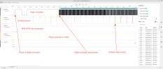
Startup_until_WiFi_connected.png
Startup_until_WiFi_connected with CGO app on my phone

Here are the steps how I looking into the communication:

Raw recording with 4-channel logic analyzer Saleae: Startup_until_WiFi_connected.sal
This file can be seen with Saleae Logic 2: Download Logic 2 Software

Here is the start sequence until gimbal is initialized: Startup_until_WiFi_connected.png

This may be the mysterious start pulse. Not clear if it is needed: Startpuls.png
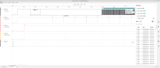
Startpuls.png
Exported files from Async Serial decoders, channel 0 to 3: Startup_until_WiFi_connected_ch[0..3].txt

Those files decoded by my cam_uart tool raw data (hex): Startup_until_WiFi_connected_Data_hex.csv
And the same better usable with Libre Office Calc (or Excel): Startup_until_WiFi_connected_Data_hex.ods

What I could decode and thougt it is worth to do: Startup_until_WiFi_connected_Data_hex.csv
And the same better usable with Libre Office Calc (or Excel): SStartup_until_WiFi_connected_Data_hex.ods

Code:
The camera comunication starts with some 1Hz haertbeat messages (MsgID 0) broadcasted by camera:
FE    05    00    02    00    00    00    00    00    00    7D    00    01


Flight controller pings with message (MsgID 1) also broadcast:
FE    03    00    01    00    00    00    01    02    00    01

And flight controller also send heartbeat (MsgID 0) 1Hz as broadcast:
FE    05    03    01    00    00    00    00    00    00    00    00    01

Then the flight controller starts to send commands to gimbal (MsgID 1) and telemetry to camera (MsgID 2) which camera should send to ST16 via WiFi.
FE    1A    9E    01    00    02    00    01    CF    26    DA    FF    10    00    6C    04    00    00    0D    00    00    00    00    00    00    00    00    08    58    02    00    00    F4    01
FE    22    05    01    00    03    00    02    00    00    00    00    00    00    00    00    00    00    00    00    00    00    00    00    00    00    00    00    00    00    00    00    00    00    00    00    00    00    00    00    00    00

After 8 sec when gimbal initialized it start to sent messages with gimbal position (MsgID:
FE    06    08    02    00    01    00    03    A2    07    09    38    9F    38

Note: All messages are shown without CRC (last 2 byte)
The files are here:
Startup_until_WiFi_connected.zip
All this stuff shows my workflow and is redundant. Maybe the *.ods files are the best to start with.
 
Last edited:
Looks like more than heartbeat, unless it is an erratic one:

Code:
06:52:58.664 -> FF 9F FC 5F FF 9F 35 ED FF 1F FF 9F BF DF EF 77 1F EF 77
06:53:06.615 -> FE FF DF EF BF 9F FF 9F 6F
06:53:09.636 -> FE BF 1F EF FF 6F 1F 6F 9F DF FB FD FC F5 FF 1F BF DF EF AF D5 DF EF 3F AB FF FA DD EF FD
06:53:16.136 -> FE 3F 5D
06:53:16.136 -> FE FF FD
06:53:16.136 -> FE D5 EF F5 DF 3F 57 47 57 D5 FF FF FF 9B FF
06:53:16.168 -> FE DF 67 F7 FB FD FF DF EF F7 FB FD
06:53:16.168 -> FE FF FF DF EF F7 FB FD
06:53:16.168 -> FE DD EF
06:53:16.168 -> FE 1F 6F FD FC D7 FF FA DF ED F5 FB FD AA DF
06:53:17.133 -> FE B7 55 EF 9D AF B5 DF C7 F5 FB 5D FC 3D 5D 4D 75 5B 75 5A FF FF FC DF E7 FF FF FF FF DF EF F7 FB FD
06:53:17.197 -> FE BF DF EF F7 FB FD
06:53:17.197 -> FE 9F B7 BF DF EF FF EA DF ED F5 FB FD
06:53:18.163 -> FE DD EF F7 DB EB FF 9D DF BF 1B 57 4F 77 FB 7D FF DF E5 E5 FB FA F9 FF FF FF FF FF DF EF F7 FB FD
06:53:18.195 -> FE FF DF EF 1F 97 B3 FF 1F B7 BF DF DF FA F7 FB DD EF F7 FB FD FA FF 5D DB FF FF D7
06:53:19.159 -> FE D5 F7 3D 5D 4B 75 5B FD
06:53:19.159 -> FE FF FD FF FC DF E7 DF EF F7 FB FD
06:53:19.191 -> FE DF EF F7 FB FD
06:53:19.191 -> FE FF FF FF FF 5F FF B7 BF DF
06:53:19.640 -> FE FF DA DF ED F5 FB DD EF F7 FB FD
06:53:20.154 -> FE FF FF D7
06:53:20.154 -> FE D5 EF 55 FB ED D5 74 5D EB 75 FB BB DF F6 F9 DF EF F7 FB FD
06:53:20.186 -> FE FF FF FF DF EF F7 FB FD

Small snippet...
How did you listen and record this? Via Arduiono?
 
The CGO3+ is connected to an esp32 module via UART using ESP SoftwareSerial. I have been testing code to control the CGO3+ gimbal but, can't seem to get it working properly. The code works, just not for my setup. Which lead me to try to simply capture the output from the CGO3+.
 
Check in the ESP32 documents how much is the bit rate error for 115.2K. If it is more than ZERO! use another type of module or change the crystal with suitable one.

CGO3+ is extremely sensitive to bit rate due to the specific of simultaneous communication.

Also I'm not sure standard UART subrotines in the Arduino will meet the necessity of this protocol.
 
Here is the Arduino code that I'm using to capture the data (actually slightly modified to stop after 30 seconds):

Code:
  Serial.begin(115200);
  CGO3Serial.begin(115200);

  byte ch;
  uint32_t starttime = 0;

  Serial.println("Begin UART capture...");
 
  while (1) {
    while ((CGO3Serial.available() > 0)) {
      if (starttime == 0) {
        starttime = millis();
      }
      ch = CGO3Serial.read();
      if (ch == 0xFE) {
        Serial.println();
        Serial.print(ch, HEX);
        Serial.print(" ");
      } else {
        Serial.print(ch, HEX);
        Serial.print(" ");
      }
      if ((millis() - starttime) >= 30000 ) {
        break;
      }
      delay(1);
    }
  }
 
  Serial.println("Capture complete.");

I haven't actually tested with the timeout. Here is the entire output from the previous test.
 

Attachments

What is CGO3serial? Which port?
I think something like that:
CGO3serial.begin(115200, SERIAL_8N1, 16, 17);
You woul have them 2 UART, one standard for debug output and another for the camera on port 16 (Rx) and port 17 (Tx).
Is Rx and Tx from ESP connected with Tx and Rx from the camera (don't trust the imprints - it may be from POV flight controller - I'm not sure with that but I can check tomorrow, following my wires.).
0xFE can also appear inside a message. You must check if it is a valid message. The next byte should be < 0x6B. I saw no longer message and those only appear when WiFi is connected and MsgID 255 is used. For the normal startup the messages are no longer than 0x22.
 
In Arduino you get to define the port names. The esp32 module has 3 UARTs. I would be using two of them SBUS output and SR24 receiver. Which is why I'm using software serial for the gimbal. I just used 0xFE since it appeared to be the starting byte for the other messages. And yes the CGO3+ RX -> ESP32 TX and CGO3+ TX->ESP32 RX.
 
Last edited:
How do this program distinguished between the 3 HW serials. With other words how do you assign for example CGO3serial to UART3 or so?

Your recording contains no only relative high values. All bytes are > 0x1A. Nowhere a 00 or 04 or so. Can this be? I still think there is something wrong with serial handling.
Every second you must have a byte combination starting with 0xFE 0x05 0x00 ....
0x05 or 0x00 you have nowhere recorded!
 
Last edited:
Software Serial does not use any of the ESP32 UARTS. According to the developer the code works to control the CGO3+ gimbal. I just have not been able to get it to work, yet. I could be that I was waiting too long to inject the CGO3+ init sequence. If I read your graph correctly, the init sequence gets sent within the 500ms mark. I've modified my capture code to inject the init sequence as early as possible, once the unit is powered up. I'm not sure what it means but, the first captured sequence is different. See attached file. And something really odd. I reversed the RX/TX, just to see if anything would be captured and it capture bytes... Not the same as when connected correctly, all of the sequences are significantly shorter. Very odd.
 

Attachments

How do this program distinguished between the 3 HW serials. With other words how do you assign for example CGO3serial to UART3 or so?

Your recording contains no only relative high values. All bytes are > 0x1A. Nowhere a 00 or 04 or so. Can this be? I still think there is something wrong with serial handling.
Every second you must have a byte combination starting with 0xFE 0x05 0x00 ....
0x05 or 0x00 you have nowhere recorded!
What is this sequence, 0xFE 0x05 0x00...?
 
Just as a probably final recommendation. Try to use hardware UART in ESP32. Try to establish at least adequate listening on one channel only.

Let me say one more time. To organize a proper communication Arduino subroutines are scrapped. You're wasting your time with this approach. Learn C!
 
The next byte should be < 0x6B. I saw no longer message and those only appear when WiFi is connected and MsgID 255 is used. For the normal startup the messages are no longer than 0x22.
Self synchronisation works flawless without any shaman dances... Just reject unpoper frames until catch a good one. Further try to not miss frames.
 
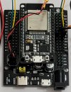
This is raw data. So what am I seeing? When the CGO3+ is disconnected, as expected, nothing is read from the connections. Here is my test setup, without CGO3+.
 

Attachments

  • 20240902_123531.jpg
    20240902_123531.jpg
    1.4 MB · Views: 6
  • 20240902_121643.jpg
    20240902_121643.jpg
    851.7 KB · Views: 6
Just as a probably final recommendation. Try to use hardware UART in ESP32. Try to establish at least adequate listening on one channel only.

Let me say one more time. To organize a proper communication Arduino subroutines are scrapped. You're wasting your time with this approach. Learn C!
I may try it afterward. The issue could be my CGO3+. At least now, I'm able to transmit the cgo3+ init sequence. I'll add the new init function to the main program and checks if it works.
 

Members online

Forum statistics

Threads
21,301
Messages
245,407
Members
28,228
Latest member
CrazeeChickn