It would appear that in current QGC daily build the attitude and compass are configurable on the main screen. Also, while cruising through the airframes defined in PX4 there is an Typhoon H480 airframe defined. Interesting...
You are using an out of date browser. It may not display this or other websites correctly.
You should upgrade or use an alternative browser.
You should upgrade or use an alternative browser.
Convert Typhoon H to PixHawk 6C Flight Controller
- Thread starter 1midniterider
- Start date
Somehow I lost my compasses in the configuration... So I reset everything back to their defaults and I'm back at square one trying to calibrate the receiver/transmitter...
Thank you... The tools you suggested worked. I had issues with the gui locking up but, the command-line tool worked very well. I was able to successfully flash my D1 Mini ESP8266 boards.No. You have only set some parameters depending on what port you want to send telemetry. See last page in attached file.
Just to illustrate what I have done, here is my test setup:
View attachment 30584
Attached: How to setup a MAVbridge.
Finally got the motors working. The ESP to FC cables needed fixing. They weren't making good contact. Now back to the radio...
h-elsner
Premium Pilot
- Joined
- Mar 23, 2016
- Messages
- 2,395
- Reaction score
- 2,156
- Location
- Bavaria / Germany
- Website
- h-elsner.mooo.com
The other day I tried to get legacy (not MAV link) telemetry data via Rx channel of the SR24 receiver. No success. I used different parameter settings and different UART ports (FrSky, UART4, TELE1), but nothing helps.
However, legacy telemetry is defined in ST24.h (from Lorenz Meier) of PX4 Autopilot. typedef struct is a little bit outdated but it is there. No glue how to get this working.
I give up at that point and will spent effort in Thunderbird firmware (trying to understand and find a way to introduce some changes in FW). My wish is to reroute MAV messages to the RealSense UART to connect an ESP8266.
I know Pöllö almost completely rewrote the RCInput.cpp code to get telemetry working. May be a place to start looking.
h-elsner
Premium Pilot
- Joined
- Mar 23, 2016
- Messages
- 2,395
- Reaction score
- 2,156
- Location
- Bavaria / Germany
- Website
- h-elsner.mooo.com
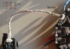
The sonar module will be supplied with 5V. What Sonar1 and Sonar2 means is hard to say because sonar is off in landed state. Measurement during flight is not possible so far.
I can only guess. From another sonar module it says that Sonar 1 is trigger and Sonar 2 is echo. Other sonar modules have PWM or analog output. UART or I²C would also possible.

Edit: Looking at PX4 descriptions for Range Finder I would start with I²C. H+ or H520 have the same sonar module.
I can only guess. From another sonar module it says that Sonar 1 is trigger and Sonar 2 is echo. Other sonar modules have PWM or analog output. UART or I²C would also possible.

Edit: Looking at PX4 descriptions for Range Finder I would start with I²C. H+ or H520 have the same sonar module.
Last edited:
After making a few adjustments on the ST16 controls I was able to calibrate the SR24/ST16. However, the Landing Gear switch works in reverse. I had mapped the Aux switch on the ST16 to kill switch, but it works in reverse. I'll need to sort those out. as well as only seeing 12 channels displayed in QGC.
I wonder if enable/disable is a function of the sensor itself or the FC?The sonar module will be supplied with 5V. What Sonar1 and Sonar2 means is hard to say because sonar is off in landed state. Measurement during flight is not possible so far.
I can only guess. From another sonar module it says that Sonar 1 is trigger and Sonar 2 is echo. Other sonar modules have PWM or analog output. UART or I²C would also possible.
View attachment 30621
Edit: Looking at PX4 descriptions for Range Finder I would start with I²C. H+ or H520 have the same sonar module.
h-elsner
Premium Pilot
- Joined
- Mar 23, 2016
- Messages
- 2,395
- Reaction score
- 2,156
- Location
- Bavaria / Germany
- Website
- h-elsner.mooo.com
It is a feature of the FC software. On the ground sonar will report constant obstacles which may lead to erratic flight after take off. I don't remember at wich heigt the sonar is enabled, maybe 10m or so.
h-elsner
Premium Pilot
- Joined
- Mar 23, 2016
- Messages
- 2,395
- Reaction score
- 2,156
- Location
- Bavaria / Germany
- Website
- h-elsner.mooo.com
You can use channel settings on ST16 to reverse aux and gear switch. It should be done only for this model that is used with PixHawk.After making a few adjustments on the ST16 controls I was able to calibrate the SR24/ST16. However, the Landing Gear switch works in reverse. I had mapped the Aux switch on the ST16 to kill switch, but it works in reverse. I'll need to sort those out. as well as only seeing 12 channels displayed in QGC.
I've set mine up very similarly and I'm also able to connect to it via wifi from an old android cellphone with QGC installed.No. You have only set some parameters depending on what port you want to send telemetry. See last page in attached file.
Just to illustrate what I have done, here is my test setup:
View attachment 30584
Attached: How to setup a MAVbridge.
Thanks... I had looked at parameters first... So, I've reversed the Arm/Disarm, the Aux and Landing Gear switches. Now, according to PixHawk/PX4 they are sending the correct signals. Odd why they were reversed.You can use channel settings on ST16 to reverse aux and gear switch. It should be done only for this model that is used with PixHawk.
So, MavLink messages are being sent but....
Bridge/Vehicle Link nearly every message being sent is lost
For Bridge/QGC Link and QGC/Bridge Link there is about a 10% loss to receive ratio. With UDP I expect some loss... I'll have to play around with the comm settings.
Bridge/Vehicle Link nearly every message being sent is lost
For Bridge/QGC Link and QGC/Bridge Link there is about a 10% loss to receive ratio. With UDP I expect some loss... I'll have to play around with the comm settings.
h-elsner
Premium Pilot
- Joined
- Mar 23, 2016
- Messages
- 2,395
- Reaction score
- 2,156
- Location
- Bavaria / Germany
- Website
- h-elsner.mooo.com
Anenna problem or interferences between 2.4GHz RC and 2.4GHz WiFi?
What I have seen in the past: If the Laptop running QGC and the transmitter on the drone are too close to each other I have an instable WiFi connection and frequently reconnects. If it I put it 2-3m away this effect disappears. Maybe the WiFi Rx/Tx is overdriven.
What I have seen in the past: If the Laptop running QGC and the transmitter on the drone are too close to each other I have an instable WiFi connection and frequently reconnects. If it I put it 2-3m away this effect disappears. Maybe the WiFi Rx/Tx is overdriven.
Both the receiver and wifi module are using 2.4GHz. I'm running QGC from an android cellphone via wifi. So, even when I'm in the next room I'm seeing packet drops. How is the connection made between the FC (wifi) and QGC? The wifi is in AP mode. What mechanism automatically connects the two devices? However, in this mode the mapping does not work. More reading to do....
h-elsner
Premium Pilot
- Joined
- Mar 23, 2016
- Messages
- 2,395
- Reaction score
- 2,156
- Location
- Bavaria / Germany
- Website
- h-elsner.mooo.com
The FC WiFi has a SSID (either the default or the one you have given). With this SSID the cell phone should connect by usual procedure to connect to any WiFi hotspot (AP). QGC will automatically detect the existing WiFi connection when MAV messages are coming in.
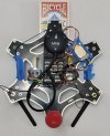
Now that I've configured and tested a few pieces. It's time to begin building the darn thing. Since, I don't own a 3D printer, I've had to rely on COTS products to modify the TH. The components I've chosen won't fit under the existing hood. So, I've opted to use upper and lower frame plates from an F550 to hold everything. The lower plate will be installed where the mainboard was located and have the power module and ESC's attached. The upper plate will be used for the PixHawk, MavLink, Drone ID and possibly the SR24 receiver, in addition to the stand for the GPS. 


