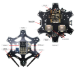
Hello Fellow Yuneec Pilot!
Join our free Yuneec community and remove this annoying banner!
Sign up

Convert Typhoon H to PixHawk 6C Flight Controller

What works:

1) The SR24 connected to the DSM port
2) GPS
3) MavLink with ESP8266 WiFi module
4) Remote ID
5) Dual 4in1 ESC, w/o ESC telemetry
6) The TH motors, of course
7) QGC via WiFI and USB, with Internet access.

What needs to work:
1) TH telemetry
2) TH Camera
3) TH Lidar
4) Flight tested
 
Last edited:
  • Like
Reactions: h-elsner
The other day I tried to get legacy (not MAV link) telemetry data via Rx channel of the SR24 receiver. No success. I used different parameter settings and different UART ports (FrSky, UART4, TELE1), but nothing helps.
However, legacy telemetry is defined in ST24.h (from Lorenz Meier) of PX4 Autopilot. typedef struct is a little bit outdated but it is there. No glue how to get this working.
I give up at that point and will spent effort in Thunderbird firmware (trying to understand and find a way to introduce some changes in FW). My wish is to reroute MAV messages to the RealSense UART to connect an ESP8266.
How goes your efforts? Question... Have you used any of those I2C -> UART converter modules? If so, what are your thoughts? So many devices seem to want to use UART, except for the TH landing gear control module, which uses PWM according to an old thread I was reading. The CGO3+ I believe can use PWM. I'll need to re-read those threads again.
 
Here is proposed layout for the modded TH. If I play my cards right I even be able to put the top TH shell on. The bottom should not be an issue...
 

Attachments

  • Typhoon H Modified Layout.png
    Typhoon H Modified Layout.png
    1.4 MB · Views: 5
Last edited:
  • Like
Reactions: h-elsner
Have you used any of those I2C -> UART converter modules
No. PixHawk and Pixracer have enough UART and I²C interfaces for all needs. YTH has only compass connected to I²C as far as I know. RealSense is UART, camera/gimbal is UART and GPS is UART.

I have tried to connect sonar module to I²C on a Raspberry Pi but i2cdetect didn't detect it as device.

Camera is controlled by CGI commands via WiFi, Gimbal is controlled by unknown data format via UART. For tilt there is a fallback to PWM after a while when serial connection could not be established.
Communication to gimbal (for tilt and yaw and whatelse) vie UART:
Conn_established.png
If UART is not uesd - fallback to PWM only for tilt:
failed_conn-PWM.png
 
  • Like
Reactions: 1midniterider
The GPS2 port on the PixHawk 6C would work great for the TH GPS/Compass as a second GPS, should I decide on using a second one. CGI for camera controls? As the question about the UART, so far I'm using TELEM2 for Remote ID, TELEM3 for MavLink, and GPS1 for the M10 GPS. I was going to use GPS2 for ESC Telemetry and holding TELEM1 in reserve for the receiver and/or telemetry. So, I'm running out of UART ports.
 
No. PixHawk and Pixracer have enough UART and I²C interfaces for all needs. YTH has only compass connected to I²C as far as I know. RealSense is UART, camera/gimbal is UART and GPS is UART.

I have tried to connect sonar module to I²C on a Raspberry Pi but i2cdetect didn't detect it as device.

Camera is controlled by CGI commands via WiFi, Gimbal is controlled by unknown data format via UART. For tilt there is a fallback to PWM after a while when serial connection could not be established.
Communication to gimbal (for tilt and yaw and whatelse) vie UART:
View attachment 30637
If UART is not uesd - fallback to PWM only for tilt:
View attachment 30638

Looks like the gimbal can be made to work.
 
Only tilt will work with this suggestion.
For a full movement, you should use a serial protocol. Done all the rest and after that, you can focus on reversing this communication. If you have at least a little bit of success I'll help you further. With raw explanations, the job was not done, so no reason for me to try one more time.
I have you had success in using the CGO3+ with something other than a Yuneec FC? If so, how was it done? As for the rest of your commentary I do not understand.
 
Still awaiting pieces and parts to fully assemble the modified TH. I the mean time I've connected and tested the remaining motors. I'll need to trim the wires once I decide on the final placement of components. I'm getting a lot of receiver disconnects. Hopefully that will clear up once I return the SR24 and its antennas to their original locations along side of the battery compartment.
 
So, looking at the CGO3+ mounting shoe, there are 4 wires that connect it to the TH:

VBAT
GRD
TX
PWM

I haven't sorted which pin goes where, I've been a bit under the weather the last few days... So, I can see how PWM could work but, how would UART work without RX?

I've sorted out a jumper cable for TH GPS and Landing Gear. Lidar and LED module, if possible, next.
 
I believe PWM is the RX when communicating via UART. If I remember correctly UART communication is attempted first and if it cannot be established PWM is used to operate the gimbal.

@h-elsner, @WTFDproject, or @Vaklin can likely give better guidance.
 
  • Like
Reactions: 1midniterider
If I remember correctly UART communication is attempted first and if it cannot be established PWM is used to operate the gimbal.
Definitely a wrong suggestion. For CGO3+ PWM mode should be initiated as in the link you have pointed. The basic mode is modified MAVLINK 57600, 8N1. The speed should be exactly the same!
For one of my Arduino-based projects, I bought 14... MHz crystals to met this.
 
UART speed drone-gimbal is 500000. What is in we can see in sensor file on ST16. The message structure is nothing we know. What we know: See user manual of Q500log2kml, page 13.
Maybe 57600 will give us new horizons? Who knows...
 
CGO3+ -> PixHawk 6C connections:

GND -> GND (PWM FMU)
VBAT -> VBAT (ESC?)
TX -> RX (UART ?)
PWM -> PWM (PWM FMU)

On a side note... I tried connecting the TH Sonar sensor to an Arduino UNO just to see if it could ID it via I2C... No joy! I'm not 100% convinced the example code is working... When I disconnected the signal connections the code would loop indefinitely... When connected only twice... If disconnected power, the code would error out, as it should... TBC...
 
very close to expecting again MAVLINK instead of I2C.

Of course, you can use any I2C Arduino-capable sensor and more than one for different directions.
Yes, I could use any other I2C sonar/lidar sensor but, the idea is use as much as possible of the original TH components. Please explain your mavlink comment.
 

New Posts

Forum statistics

Threads
21,009
Messages
242,235
Members
27,579
Latest member
Nick67Grymes