Hello Fellow Yuneec Pilot!
Join our free Yuneec community and remove this annoying banner!
Sign up

H520 battery issue

...... but I am not sure if I should just plug into each end or should the positive be on the one end and negative needs to go into each of the slots.
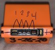
Neither.
Each adjacent contact is a cell with a positive side and a negative side for THAT cell. The drawing has two lines leading from each cell number. Each line leads to either the positive or negative for that numbered cell. Each connection point (except the two on the ends) is the positive contact for one cell and the negative contact for the next. The drawing notes the negative on the left and the positive on the right. The final positive side has two contacts. One matches the connector in the OEM charger, the other matches the connector in the aircraft.
A 9v battery is probably too much for an individual cell and not enough for the whole battery pack. Getting "creative" and trying to charge two cells at a time with the 9v might get a little risky.
Many folks use a 5v USB charger with the plug cut off to charge one cell at a time until the overall pack has enough charge for the normal charger to start.
1FB3081A-D27C-412B-8754-DF9DFC6E20E4.jpeg
 
  • Like
Reactions: Steve Carr
The GiFi packs have the same cell layout as the Power4 and Power4P packs from Yuneec. The attached document should help you understand what @WTFDproject was explaining in the previous post.

This is what the USB cable mod will look like.
 

Attachments

  • Power4 battery terminals.pdf
    435.4 KB · Views: 4
  • Like
Reactions: rconiv
Neither.
Each adjacent contact is a cell with a positive side and a negative side for THAT cell. The drawing has two lines leading from each cell number. Each line leads to either the positive or negative for that numbered cell. Each connection point (except the two on the ends) is the positive contact for one cell and the negative contact for the next. The drawing notes the negative on the left and the positive on the right. The final positive side has two contacts. One matches the connector in the OEM charger, the other matches the connector in the aircraft.
A 9v battery is probably too much for an individual cell and not enough for the whole battery pack. Getting "creative" and trying to charge two cells at a time with the 9v might get a little risky.
Many folks use a 5v USB charger with the plug cut off to charge one cell at a time until the overall pack has enough charge for the normal charger to start.

View attachment 30315
Thank you, that makes more sense.
 
It depends on how low the voltage is on each cell and what the amperage is that the charging block can output.

The cells in these packs are fairly large so it will take time to bring them up. I would suggest measuring the cell with the Fluke, charge for 3 minutes, then measure the voltage again. You can then gauge how long you should charge that cell.

You want to get all 4 cells to an equal voltage of 3.2V to 3.5V so the charger will be able to then charge the pack automatically.

Be cautious doing this and watch for any signs of overheating and out gassing (puffiness).
 
Depending on how depleted any individual cell became I would suggest doing test flights where you only hover a few feet off the ground and monitor the battery state constantly. A weakened cell can cause the pack to deplete to dangerous levels very quickly.

If this goes okay for a couple charging cycles you can start adding some vertical ascents and descents to the low hover and see how that affects the battery state.

@h-elsner has a simple software tool for checking the battery from the flightlogs. It would be a good idea to use it and determine if these packs need to be retired from flight duty. Battery check from this link Downloads

If you need help interpreting the data just post the results here.
 

New Posts

Members online

No members online now.

Forum statistics

Threads
20,977
Messages
241,829
Members
27,383
Latest member
shalinishn18