Hello Fellow Yuneec Pilot!
Join our free Yuneec community and remove this annoying banner!
Sign up

Problem Mantis G

Joined
Aug 15, 2021
Messages
31
Reaction score
9
Age
54
Hi.
Another drone Mantis G after about 400 to 480 meters in different terrain (correctly set antennas) the drone completely breaks the image and only after returning to about 440 meters it regains it, when previously it flew in favorable terrain up to 900 meters (more reportedly the customer did not fly).

I swapped the controller from another drone but it was still the same.

Where could be the problem here.

Thank you very much for your reply
 
I suspect that the issue may be with the antennas found in the rear arms of aircraft. Either a bit of fine oxidation on the connectors, chafing of the shielding at the pivot point, or damage to the rear arm from striking objects.

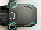
Unfold the arms and place the Mantis G (MG) on its back. Using a #00 Phillips remove the screws on either side that hold the top cover on.
FFFB837D-A5C8-4AC5-AAEF-EB6C67ECA991.jpeg

Now start at the rear of the top cover and pop both sides loose and then near the front use a plastic swedge (heavy guitar pick works well) work the front of the cover loose without breaking the front tabs.
AB700B69-EE9D-4062-A613-D1BA8C8796A5.jpeg

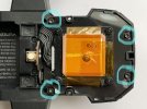
Remove these four screws using a 1.5mm hex.
C0E4C54E-5C7E-41A1-A2F0-9356F018A923.jpeg

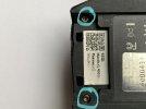
Remove these two screws at the back of the battery bay (1.5mm hex).
55D41EA6-31E3-435D-AA31-1AFFAE7E1D9A.jpeg

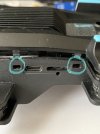
Remove these two screws from the bottom of the rear arms (1.5mm hex).
6578770A-48FE-4107-A7DC-C8A0E4495041.jpeg

Start at the rear behind the screws removed at the battery bay and start separating the bottom cover. On either side use a small flat blade screwdriver to release the tabs and continue forward working the bottom cover off.
90500803-9241-4925-A39A-A44A027A7E2D.jpeg

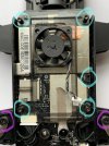
Remove the connector for the fan and the four screws circled in cyan as well as the two Phillips screws circled in magenta.
DDA9D945-FB27-4896-95EE-3E781BA44EB7.jpeg

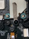
Remove the antenna connectors.
C2CF8755-39E5-4123-9E3D-8941CDF04536.jpeg

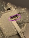
Inspect the antenna cables for chafing. Remove the metal spring loaded pivot pins and pull the arms out a bit to check the cables where they enter the rear arms.
E327DD9D-CE8B-4965-9E02-D4CED0177B68.jpeg

At the pivot is the most likely area for damage to the antenna cables. Any wear to the shielding there can cause weak signal transfer. The antennas may be an integral part of the rear arms.

Reassembly is in reverse order. Installing the pivot pins will require pliers of some type to turn them to align with the screw holes while downward pressure is applied to seat them.
 
Last edited:
  • Like
Reactions: Kiril
I suspect that the issue may be with the antennas found in the rear arms of aircraft. Either a bit of fine oxidation on the connectors, chafing of the shielding at the pivot point, or damage to the rear arm from striking objects.

Unfold the arms and place the Mantis G (MG) on its back. Using a #00 Phillips remove the screws on either side that hold the top cover on.
View attachment 28355

Now start at the rear of the top cover and pop both sides loose and then near the front use a plastic swedge (heavy guitar pick works well) work the front of the cover loose without breaking the front tabs.
View attachment 28356

Remove these four screws using a 1.5mm hex.
View attachment 28357

Remove these two screws at the back of the battery bay (1.5mm hex).
View attachment 28358

Remove these two screws from the bottom of the rear arms (1.5mm hex).
View attachment 28359

Start at the rear behind the screws removed at the battery bay and start separating the bottom cover. On either side use a small flat blade screwdriver to release the tabs and continue forward working the bottom cover off.
View attachment 28360

Remove the connector for the fan and the four screws circled in cyan as well as the two Phillips screws circled in magenta.
View attachment 28361

Remove the antenna connectors.
View attachment 28362

Inspect the antenna cables for chafing. Remove the metal spring loaded pivot pins and pull the arms out a bit to check the cables where they enter the rear arms.
View attachment 28363

At the pivot is the most likely area for damage to the antenna cables. Any wear to the shielding there can cause weak signal transfer. The antennas may be an integral part of the rear arms.

Reassembly is in reverse order. Installing the pivot pins will require pliers of some type to turn them to align with the screw holes while downward pressure is applied to seat them.
Doomeister , quick question if you don't mind ? My grandad was flying his mantis g and managed to lose it in a cornfield due to it disconnecting mid flight ; is there a way to check the flight logs to see where gps last pinged
 
Possibly. Retrieve the logs as described in:
Be sure the files are zipped, and upload them here to the Forum.
 

Members online

No members online now.

Forum statistics

Threads
21,327
Messages
245,660
Members
28,265
Latest member
Maykel