Hello Fellow Yuneec Pilot!
Join our free Yuneec community and remove this annoying banner!
Sign up

Update bricked, and gui doesn't work....

The blue diodes are all working, the one in yellow has a dead short. Zero voltage drop accross it, when it should read 5.3 ish voltage drop. Not sure if that's the only bad part or not. I'll have to swap it with a through hole, but it should tell me if that's the only bad part or not.
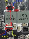
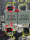
The one in yellow reads pretty much 5.3 on both sides on this board. The outside varies a little between 5.3 and 5.29, but still pretty close to no voltage drop. I've never traced this side to see what it powers.
This board seems to work normally. It has not been installed in anything since I have had it, but it powers up and looks good on the GUI.
 
Found ONE pack that can be here tomorrow I ordered it. It shouldn't read that on both sides. Either way I needed diodes so....

I'll do a few more tests here in a few minutes. So much going on I have go go back and forth several times.

Positive side the new USB cable worked.
 
  • Like
Reactions: WTFDproject
Just for a little clarification. So we are on the same page, assuming that the one Diode is fine or is completely unrelated.

Maybe I'll just swap them both see what happens.

The other board you showed that has the markings uses SS510 Schottky. Similar specs, 100V 5A.

Out of curiosity, what do you show for voltage ACCROSS those diodes when the power button is on rather than spot readings?
 

Attachments

  • TH FC Power Voltage Reaedings.jpg
    TH FC Power Voltage Reaedings.jpg
    413.1 KB · Views: 4
  • TH FC Power Voltage Reaedings 2.jpg
    TH FC Power Voltage Reaedings 2.jpg
    417.6 KB · Views: 3
Last edited:
Well now that's VERY interesting. That one diode is the only thing thats different. Everything else is within tolerance level. I'll swap that one with the SS510 tomorrow if there isn't an exact match in the pack, since the SS510 is on that other board you were showing. Likely the same exact thing with obfuscation markings. Having that be that far off could definately prevent power from getting where it needs to go. We shall see if that works.
 
Last edited:
  • Like
Reactions: WTFDproject
I'll swap that one with the SS510 tomorrow if there isn't an exact match in the pack,....
Another thought might be to pull the OEM chip from the RealSense power source and use it for the flight control. Then use the mismatch chip to restore the RealSense Power if desired.
I agree there is probably no real difference, but OEM on flight related circuits feels more comfortable.
 
I was thinking that if nothing else but to give me something to do while waiting. Hopefully that's all that powers is realsense, since my realsense isn't functional.

Not really concerned about OEM to be honest, as it's a diode. Sole purpose is to allow current in one direction only. Schottky diodes just shut off faster, and have a .2V drop rather than .5V drop of a regular diode. Manufacturers change out specific diodes and other components with different part numbers based on supply.

However I did still go ahead and swap it over. Now the voltages are where they should be on that side. The beep is gone, but the power button stays lit up if I hold it(it never lit up before). I suspect the missing diode does more than power the real sense. When the package shows up, I'll drop in an SS510 and find out.

Whether or not it resolves the issue, it still needed to be replaced.
 
Last edited:
..... I did still go ahead and swap it over. Now the voltages are where they should be on that side. The beep is gone, but the power button stays lit up if I hold it(it never lit up before).
The power button should light up and stay lit anytime the TH is powered on. If that is what you are seeing, it is normal.

Does the system seem functional now?
Can you see the TH values on the GUI?

If you have assembled the drone:
Does GPS find Satellites and acquire?
Do motors run from the GUI test?
Will motors start from the controller start button?
 
It was not staying lit before but it is now. Everything is back together. Still doesn't see any values in the GUI at all. The update side works(tried with an FC you sent).

I'm going to go outside with it and see if itll bind and hover a little.

Ok well no takeoff. Something isn't quite right. It's close. I'm getting no telemetry from the drone itself. I marked everything so everything is hooked back up where it's supposed to go. There is one spot that I remember a connector going to, but for the life of me I can't find the wires that go there. Circled in yellow. I'm assuming that is the most likely culprit.


Attachments

  • missing connector.jpg
    missing connector.jpg
    688.7 KB · Views: 4
Last edited:
  • Like
Reactions: WTFDproject
Still doesn't see any values in the GUI at all. The update side works(tried with an FC you sent).
Did you do that firmware update to the FC while it was installed in the TH and is it still the one installed, and with the USB extension plugged in?
I ask because of the number of times I've installed the top shell without plugging the USB extension into the back edge of the FC board.
 
That firmware update was to one of the FC boards you sent. It was not installed in the Typhoon. The one in the Typhoon now is the original.
 
Figured it was something important LOL. Now I just gotta figure out why TF I can't find it lol. Where it comes from on the drone. Gonna guess from the Antennas.
 
The receiver is mounted on the left outside the battery box. The wires run up and over, meaning they were likely laying on top of the battery box when you laid the main ESC board on it. The wires are now likely trapped between the top of the battery box and the main ESC Board. (promise you won't ask why I was so quick to suggest that. :rolleyes: )
 
Close, it was trapped between the frame and the little board at the back there. 😂😂😂

I can't remember which IMU is plugged in so I'm gonna leave the bottom shell off and attach the top with only 2 screws. If it's good I'll put it all back as is. The clips that hold the shell together are almost all missing, and I don't wanna deal with all the screws yet if I gotta swap IMU again lol.

I'm gonna use one of those FC's and put the thunderbird on it. See what's up.
 
  • Like
Reactions: WTFDproject
First try failed, then I swapped the other IMU in and it took right off.

Happy Camper. Appreciate all the help.

Here is a video from my phone. I' post a video or two from the flight, as well as a series of photos I took for a panorama as soon as I find my SD Card reader.

VERY windy out here right now too.

 
Totally screwed up and deleted the videos. Formatted the card actually. I got some nice photos from the flight though.

Special thanks to everyone who helped get this thing back up in the air. In the end I needed a new Schottky Diode. Soldered it in and good to go. Thankfully I'm comfortable with soldering SMC. This is harder than Avionics, because at least with Avionics you have Schematics lol.
 

Attachments

  • Lakeview from 200 Feet.jpg
    Lakeview from 200 Feet.jpg
    9 MB · Views: 5
  • Tanwax From the Sky 1.jpg
    Tanwax From the Sky 1.jpg
    9.3 MB · Views: 5
  • Tanwax From the Sky 2.jpg
    Tanwax From the Sky 2.jpg
    10.9 MB · Views: 4

New Posts

Members online

Forum statistics

Threads
21,016
Messages
242,436
Members
27,604
Latest member
Erik de Vos