OK...I did the ol' "Found a tree, knocked the gimbal off, broke the wires" thing. I was going to perform the repairs and put in a break away connection mid point in the leads from the gimbal mount to the gimbal so no more ripped wires off the circuit board the next time I crash.
I have the exact same problem. Your photos are identical to mine. My drone did not fine a tree all by itself though, it had help. It came into contact with a hawk that apparently does not approve of drones. The attack put the drone in the top of a 100 foot pine tree. That was back on February 6. I have been unable to locate the drone with binoculars or an extensive ground searching for about a week. I than started finding pieces of prop. Last night we had a severe storm with wind 60 mph gusts that finally made the tree give up the aircraft. I went searching today and found more prop, the 4k camera and gimbal, and the drone in the top of a 12 foot tree which I was able to convince to give up my aircraft.
I have the same problem as mentioned here (identical) where the wires and trace from the circuit board came off. I'm glad someone is able to provide the pinout and I will make the same repair to the back of the connector. This appears to be a common problem. perhaps Yuneec should consider making the cables breakaway to prevent them from getting ripped off the board if the camera separates.
I will also say thanks to George for providing the pinout. I was contemplating all my options for board / pigtail replacement. This will make it a relatively easy fix.
John O'
So I finally got a hold of all the crap I needed to perform the repairs, and that one little inlaid wire that came loose from the circuit board, broke off. And everything was going so well too.
Getting ready to start.
Finished the break away wires for the gimbal mount
The inlaid wire and copper pad that ripped loose of the board.
Got 2 of the lower wire soldered on, then that one that pulled the pad and wire loose from the board broke.
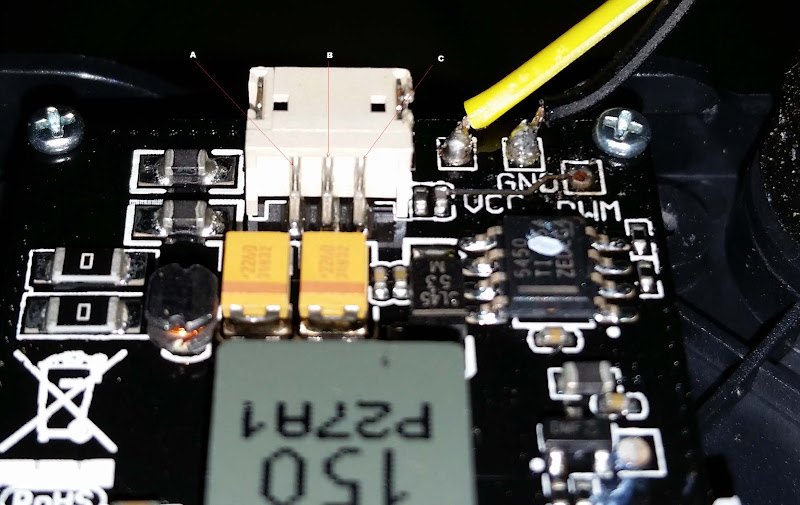
SO - The current plan is to solder the PWM wire to the back of the pigtail connection port, but I need to know which lead is what.
Edited - Found the info - Thanks George for the tip
Left to right,
A ~ GND
B ~ VCC
C ~ PWM
So now that I found out which pin on the back of the connector I need to go to...
Ran the wires under the board and up from behind, then through the cover.
Here is is all assembled and connected. The pins keep a good connection, and should pull free in the event of another gimbal mount separation. No I did not do a inertia test to verify. I will take it on faith that the solder joints and the wires will hold longer than the pins in the sockets.
Probably going to void the warranty on the other (yes, I bought a another Q500 set) and do this pre-emptively, so the board does not get damaged by ripping the solder joints out.
I first tried to test in my steady grip, and everything was working, but the app. I then attached it to my Q and everything works as normal.