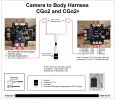
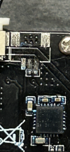
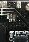
Hi everyone, I wonder if anyone can help me after my unfortunate crash that has damaged the cgo2 power board. Unfortunately the plug that goes to the top board from the bird has come away. Is there anywhere in the UK that might be able to help get this sorted? I can’t find any replacement boards anywhere and I can only find a replacement cgo2 from eBay at £180.
You are using an out of date browser. It may not display this or other websites correctly.
You should upgrade or use an alternative browser.
You should upgrade or use an alternative browser.
Cgo2 power board
- Thread starter Dezt1980
- Start date
Last edited:
Probably means something crossed when it ripped out. The board may be beyond repair. Can't tell without having it in hand. The pattern of the beep code might tell us something, but it will probably have to go for repair.
You can contact Yuneec UK to see if they can still help with CG02.
CONTACT US
CGo3 will also work but requires a pigtail cable if your Q500 is not a 4K.
You can contact Yuneec UK to see if they can still help with CG02.
CONTACT US
CGo3 will also work but requires a pigtail cable if your Q500 is not a 4K.
h-elsner
Premium Pilot
- Joined
- Mar 23, 2016
- Messages
- 2,392
- Reaction score
- 2,152
- Location
- Bavaria / Germany
- Website
- h-elsner.mooo.com
This might get confusing, but you may need to know it to ensure the correct wires are using the correct drone-side pin connections.
The drawing provided by @h-elsner shows the connector ground pad. That is correct and accurate. The confusion comes that the WIRE associated with that pad is NOT connected to ground in the Q500. It is connected to an empty pin on the drone end. (On the board, it is connected by board tracing to the actual ground wire on the other side of the board.)
The pin position and names on these two drawing sets have always been correct. However, the pin numbers on the drone side were edited today to make the pin numbers consistent between the CGo2 drawing and the Q500 drawings.
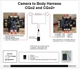
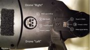
Sorry for making this confusing but wanted to ensure that if you did happen to notice the anomaly you would not try to connect the wire related to the connector ground directly to the actual drone ground. Or think it was a possible source of the problem.
The attached PDF document also shows the drone connections on the inside of the drone shell to further
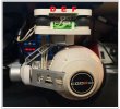
This last image is just an example of a CG02 that has lost its "D" connector and is running normally on the "E":
Attachments
Last edited:
h-elsner
Premium Pilot
- Joined
- Mar 23, 2016
- Messages
- 2,392
- Reaction score
- 2,152
- Location
- Bavaria / Germany
- Website
- h-elsner.mooo.com
This open wire to pin3 of the Q500 connector is connected to ground at the controller board. It may be open on the Q500 side but it is twisted to the PWM signal wire. This gives the signal wire a proper impedance and makes it possible to carry signals in higher frequencies with simple wires (twisted pair).
I don't know whether it is really necessary to carry the ground or not, but it can't do any harm.
By the way, all those twisted wires used in drones (i.e. to nGPS module but also others) are not only for good looking but makes sense for good signal quality.
I don't know whether it is really necessary to carry the ground or not, but it can't do any harm.
By the way, all those twisted wires used in drones (i.e. to nGPS module but also others) are not only for good looking but makes sense for good signal quality.
Thanks for all the help and suggestions on this. I’ve contacted Yuneec UK and they’ve got back to me to tell me that they can’t swap boards as they’re programmed to the camera and gimbal. It’s time to break out the soldering iron I think.
@WTFDproject how did you get everything working using the E connector? Did you have to reroute a cable or 2
@WTFDproject how did you get everything working using the E connector? Did you have to reroute a cable or 2
No. They just work as they are. The fact that yours does not work strongly implies there is other damage to the board. If the board does not work after reconnecting the wires, it may be a lost cause.Thanks for all the help and suggestions on this. I’ve contacted Yuneec UK and they’ve got back to me to tell me that they can’t swap boards as they’re programmed to the camera and gimbal. It’s time to break out the soldering iron I think.
@WTFDproject how did you get everything working using the E connector? Did you have to reroute a cable or 2
,,,,,,,,,,,,,,, It beeps and flashes red which I’m not sure what that means.
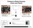
If the beeps are in a "High/Low followed by three short" pattern, it is probably reporting a camera IMU problem. Damage to the wires or IMU connector on the board would be a good place to look. See connector "G" on the newly revised drawing below:Great, I think a full tear down is going to be in order now to check other areas.
- Joined
- Jan 4, 2019
- Messages
- 490
- Reaction score
- 689
- Location
- Citrus Heights, CA
- Website
- yuneecskins.com
Why not just put a CGO3 4K HD Camera on it? Problem solved... The CGO2 Cameras are more prone to issues than the CGO3...
That’s the plan B, I’ve seen a few from Germany for just over £100, just need to sneak it past the wife.
Similar threads
- Replies
- 7
- Views
- 1K
- Replies
- 9
- Views
- 408
- Replies
- 1
- Views
- 2K
- Replies
- 11
- Views
- 1K


