Hello Fellow Yuneec Pilot!
Join our free Yuneec community and remove this annoying banner!
Sign up

H920+ Service/Repair Manual

FLDirector19

Premium Pilot
Joined
May 29, 2019
Messages
93
Reaction score
17
Age
70
Greetings & Salutations!!

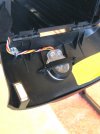
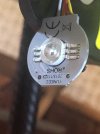
Might anyone know where I can get a copy (hard copy or digital) of the H920+ Service Guide?
I travel 11/12 of the year, and often in remote parts of the country, making it difficult to get it repaired, should the need arise. It also would aid in troubleshooting issues.
I’d be willing to sign a NDA.

Thanks.
 
Last edited:
To our knowledge there was never one released to the public and the repair facilities sign an NDA with Yuneec. If you ever come across any documents like that for any Yuneec products PLEASE share it here on the forum. We will be doing likewise.
 
  • Like
Reactions: FLDirector19
Can you help me get the top cover off the H920+?
I need to check for broken/loose contact points.
 
Look for machine screws from the bottom into the top. Most likely on either side of the leg openings. They will most likely need a hex key wrench. I know @Yuneec Newbe removed the top cover from his recently.
 
Look for machine screws from the bottom into the top. Most likely on either side of the leg openings. They will most likely need a hex key wrench. I know @Yuneec Newbe removed the top cover from his recently.
Thanks. I found and removed all of the T8 screws. The top needed to have the three wires for each arm removed for the top to come off (plus the GPS cable.)

In looking at the guts, without a schematic, I need to trace wires to components. One problem I had was the LED in the back of the aircraft was connected to the GPS and the GPS was connected to the LED connector.

I don’t see a set of wires to attach to the IMU, but that doesn’t necessarily mean it’s missing (hopefully a more knowledgeable pilot will help me verify the connectors on the FCO.)
 
Tornado H920 & H920-Plus Top Shell Removal;
Tornado H920 Top Shell 10.1.png
I have seen Both ESC-Power Distribution Boards in either Model, looks like they may have just updated Firmware to Convert H920 to an H920-Plus
Tornado H920 vs H920+ ESC.png

H920+ 10.1.png

H920+Wiring Detail 10.1.png
Yunnec Skins How to Frame 10.1.png
 
Last edited:
Okay… next riddle:

The wire bundle from the status light was plugged into the GPS connector and the GPS wire bundle was plugged into the LED connector.

Could having them reversed have burned out either the LED or FCO?

After I replaced each wire to its appropriate connector, started the ST16, switched on the H920+. The LED had a very faint red/blue/green glow… resembling a short.

How can I check them?
Would you advise I replace the status LED & FCO?

Thanks!
 
Good Morning Pilots,
My issue was with the LED it was non functional. When the cover was removed the wire was not connected. As luck would have it I had purchased 2 aircraft. So I removed the #2 (New unused) aircraft cover to see the wire configuration. There were 2 open connections of the 4. I did not take pictures. looking into another New H920+ I am going to wait on the bottom of the market. I am sure I will be into these again aircraft and will get photos on the next go round.
 
  • Like
Reactions: FLDirector19
Is the battery fully charged?
What do you see/hear on the ST16 and H920 if you unplug the LED and power up?
Thanks!
I will verify the battery charge and do as you suggested. Standby for results.
 
Thanks!
I will verify the battery charge and do as you suggested. Standby for results.
Can you post a photo of the Status LED assembly where the wires and backside (internal) shows? We can likely be able to make out enough to be able to test it with a 5VDC source to tell if the LED is bad or not.
 
Thanks for the added info John. Any chance you know the pinout for the Status LED assembly? Usually a +5V common and then ground is switched to the appropriate wires for red, green, and blue to make all of the possible colors. If we know that the functionality of the LED’s can be tested.
 
Is the battery fully charged?
What do you see/hear on the ST16 and H920 if you unplug the LED and power up?
I used two batteries (See attached photos).
The display on the ST16 (see photo), while nothing happened on the H920+. There were a few LEDs lit on the main board, however.

Thoughts?
 

Attachments

  • 2544A818-4049-4F9B-8394-E751FA60A652.jpeg
    2544A818-4049-4F9B-8394-E751FA60A652.jpeg
    1.6 MB · Views: 25
  • 9A5C7B37-1DB4-41D5-A5D7-807D867BD0D3.jpeg
    9A5C7B37-1DB4-41D5-A5D7-807D867BD0D3.jpeg
    2.6 MB · Views: 26
  • DADBF13B-029A-4F0D-8737-281A58F060AB.jpeg
    DADBF13B-029A-4F0D-8737-281A58F060AB.jpeg
    1.8 MB · Views: 24
Can you post a photo of the Status LED assembly where the wires and backside (internal) shows? We can likely be able to make out enough to be able to test it with a 5VDC source to tell if the LED is bad or not.
As requested…
 

Attachments

  • DE312793-4AB2-447D-8611-E08205F8E39A.jpeg
    DE312793-4AB2-447D-8611-E08205F8E39A.jpeg
    1.4 MB · Views: 30
  • A675F92F-9674-4236-9F0C-30896BB2CFBC.jpeg
    A675F92F-9674-4236-9F0C-30896BB2CFBC.jpeg
    966 KB · Views: 30
  • ACC57699-73F3-4865-ADD1-1680CA2C55FC.jpeg
    ACC57699-73F3-4865-ADD1-1680CA2C55FC.jpeg
    1.1 MB · Views: 30
As requested…
If you unmount the LED casing, can the wires be traced through the clear casing? Or possibly be removed from the clear casing? If I can see the circuitry I may be able to figure out how to test it for functionality.
 
If you unmount the LED casing, can the wires be traced through the clear casing? Or possibly be removed from the clear casing? If I can see the circuitry I may be able to figure out how to test it for functionality.
Here it is…
 

Attachments

  • 7F6874CD-F29E-41AD-9F56-63A51ACA1A09.jpeg
    7F6874CD-F29E-41AD-9F56-63A51ACA1A09.jpeg
    671.3 KB · Views: 28
  • DE15C6A2-9CEE-44BC-9322-1ACD496DF1FE.jpeg
    DE15C6A2-9CEE-44BC-9322-1ACD496DF1FE.jpeg
    870.2 KB · Views: 28
Thanks for the photos! I can’t really tell any circuit traces from the photos. This circuit is a lot more active than most LED indicators as seen by the driver IC’s and the coils. In the photo of the circuitry side the left driver appears as though it may have debris on it or it is damaged.

Since there is this much circuitry my instinct tells me the power is on the black and white wires and the color select are the red, orange, and yellow wires.

I will try and get a schematic or info on the FCO pinout to be able to test this.

This link appears to be like the LED itself with six leads. LED RGB 9W 6-Pin - ProtoSupplies

I have feelers out for more information. When I get back from golf today I will generate a diagram and troubleshooting steps to at least test the LED itself.
 
Last edited:

New Posts

Members online

No members online now.

Forum statistics

Threads
20,977
Messages
241,829
Members
27,383
Latest member
wiebeedigital