Did someone redraw from the main PCB the schematic diagram? I have a raw idea to use it for other purposes, as a mediator between the USB camera and the Wi-Fi. I know, the firmware should be rewritten. This is the next step, where I'll look for cooperation. In the last time very good and relatively cheap thermal camera modules are available on the market.


You are using an out of date browser. It may not display this or other websites correctly.
You should upgrade or use an alternative browser.
You should upgrade or use an alternative browser.
Looking for a CGO3 / 3+ schematic diagram.
- Thread starter Vaklin
- Start date
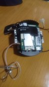

I don't know how the signal routing works at all. I do know the signal from the thermal image does not go to the main camera processor board. At least not directly, as the visible light camera does. The ribbon from the thermal camera only goes directly to the green WIFI board. The CGoET WiFi board has a small extension on the right side with a connector for the Thermal camera ribbon. Another small extension at the upper left corner. The board is slightly wider overall. It has more SMDs and in a somewhat different arrangement when compared to a standard CGo3 type WiFi Board. I think you will need to find a schematic specifically for a CGoET WiFi board to have the information you seek.
There is some physical damage to the CGoET board in this picture, but I think it illustrates some of the visible differences:

There is some physical damage to the CGoET board in this picture, but I think it illustrates some of the visible differences:
Last edited:
Thank you for the information. Exactly I asked for a different thing. The board has components, which can be used in a versatile style. Because the board has already 5.8 WiFi, a card slot, a USB port, an RS232 port, and so on, it is a good candidate for development. An exact schematic is necessary to know what we have and how it is connected.
Just for an example, has the processor master USB port or hasn't it?
Just for an example, has the processor master USB port or hasn't it?
This is the camera WiFi board. The main board is as an egg and is placed on the opposite side of the radiator. Can you post pictures from both sides of it too?but I think it illustrates some of the visible differences:

h-elsner
Premium Pilot
- Joined
- Mar 23, 2016
- Messages
- 2,703
- Reaction score
- 2,575
- Location
- Bavaria / Germany
- Website
- h-elsner.mooo.com
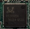
This is the WiFi system on a chip. I think it needs control from processor on Video card. As processor an Abarella S2E chip is running. It is based on a a dual core Cortex A9 CPU.
If I disconnect the WiFi card fom video card (ribbon cable) it is dead, no WiFi.
The datasheet for RTL8192 is here:

br HE
If I disconnect the WiFi card fom video card (ribbon cable) it is dead, no WiFi.
The datasheet for RTL8192 is here:
RTL8192CE PDF
Part #: RTL8192CE. Description: SINGLE-CHIP IEEE 802.11b/g/n 2T2R WLAN CONTROLLER w/PCI EXPRESS INTERFACE. File Size: 269.96 Kbytes. Manufacturer: Realtek Semiconductor Corp..
pdf1.alldatasheet.com
br HE
1. CE and DU are different.
2. Can't check right now, but (IMHO) the WiFi board in the ST16 has the same IC, where is no Ambarella to drive it.
3. USB port on both PCB and an SD card port is not connected to the mainboard for video processing.
4. CGO-ET IR part is directly connected to the WiFi board.
5. E and A versions are not related to the video.
6. We can change E to A and vice versa. I didn't test this but read for this possibility here.
7. Video chip is obligated to process the video, not to prepare an RSTP stream.
... and so on.
All of these talks here is a processor inside.
The target is to use InfiRay T2 Search on the drone. It is a UVC camera with a known set of commands. 26 gram only, 150 meters distance to view. 300 EUR on the second-hand market. The best candidate. Of course, the best will be if the overall thing imitates some known camera for the ST16, and important is to get data from the UART to prepare the right EXIF for every picture, but this is programmatically soluble.
My one should arrive in the next week. I'll prepare a sepparrated topic.
2. Can't check right now, but (IMHO) the WiFi board in the ST16 has the same IC, where is no Ambarella to drive it.
3. USB port on both PCB and an SD card port is not connected to the mainboard for video processing.
4. CGO-ET IR part is directly connected to the WiFi board.
5. E and A versions are not related to the video.
6. We can change E to A and vice versa. I didn't test this but read for this possibility here.
7. Video chip is obligated to process the video, not to prepare an RSTP stream.
... and so on.
All of these talks here is a processor inside.
This says only about WiFi up after a proper initialization of the whole system.If I disconnect the WiFi card fom video card (ribbon cable) it is dead, no WiFi.
The target is to use InfiRay T2 Search on the drone. It is a UVC camera with a known set of commands. 26 gram only, 150 meters distance to view. 300 EUR on the second-hand market. The best candidate. Of course, the best will be if the overall thing imitates some known camera for the ST16, and important is to get data from the UART to prepare the right EXIF for every picture, but this is programmatically soluble.
My one should arrive in the next week. I'll prepare a sepparrated topic.
h-elsner
Premium Pilot
- Joined
- Mar 23, 2016
- Messages
- 2,703
- Reaction score
- 2,575
- Location
- Bavaria / Germany
- Website
- h-elsner.mooo.com
I'm not saying an Abarella needs but an extra processor to initialize and control the WiFi chip, no matter what it is. My guess: the Abarella CPU for CGO3, the STM32 in ST16.
If you're right, the solution is not more complicated than the first one. Just is necessary a mediator between the video interface and the WIFi board. There are a lot of possibilities. Let me first see if the camera is so good, as it's mentioned.
Received the InfiRay T2 Search in the last few days. Tested on the phone with a USB C. Great camera. Ordered C to 2.0, but it is still on the road. Still have no idea how is the best to organize the next steps, but for me will be better to have something, which will be accessible via the ST16. I'll think.
For now, the topic is to read and understood the UVC 1.5 Class specification.
For now, the topic is to read and understood the UVC 1.5 Class specification.
Tested on PC. The palette is "white is hot, black is cold" as default. Zero lag in the stream. Some simple program for Windows to send commands to UVC to try different palettes?Ordered C to 2.0, but it is still on the road.
Version: V1.00
Appendix3 Controlling protocol
The controlling protocol is the Zoom (Absolute) of the UVC protocol. Controlling command is 2 bytes in total, the low-byte is the parameter, the high-byte is the register's address.
For example, shutter working command 0x8000.
Detailed commands:
Register - 0x80
Number Address Parameter Description
1 0x00 Shutter NUC
2 0x01 Background NUC
3 0x02 Detector original value output
4 0x05 Image data output
5 0x20 Normal temperature range
6 0x21 High temperature range
7 0x27 16 byte parallel image data output
8 0x28 8 byte parallel image data output
9 0x29 16 byte parallel image data and temperature data output
10 0x30 8 byte parallel image data and temperature data output
11 0xFE Save setting parameters
12 0x88 0-7 Palette
Sony subLVDS description wanted. It can be reverted from some public projects, but it better is to read the manufacturer's papers. This approach gives a chance to involve deeper in the mind of the document's owner.
And one more question. Did someone had seen somewhere a subLVDS imitator/simulator/fake device etc.? For the first instance, I'd like to replace temporary the sensor in the CGO3+ with something else. A static picture is OK.
And one more question. Did someone had seen somewhere a subLVDS imitator/simulator/fake device etc.? For the first instance, I'd like to replace temporary the sensor in the CGO3+ with something else. A static picture is OK.
A step back to do the first tests.
I'm looking for a USB UVC HOST device with a converter to PAL video. Not so deep googling gives me nothing. Everything is a capture device, doesn't matter how the manufacturer named it.
The first test chain can be InfiRay T2 Search -> USB host -> MPEG to PAL -> MK58. All this will be mounted on the CGO3+ gimbal. Pallete will be defined on the ground before the flight.
This will be the less effort solution because USB to subLVDI is a simple mirage with my personal coding skills.
I bought a VNC2 development board, which can produce a still image as BMP to test the overall possibility to read this camera. It will come in the next week or so. If this is successful, the next will be successful too.
Did someone store this one?

 yuneec-forum.com
Typhoon Camera (android app) with MK58 support
Hi all, so this is the very first public release V. 0.4.0 of my Android app called Typhoon Camera. It currently supports only a few things, so it...
h-elsner
Premium Pilot
- Joined
- Mar 23, 2016
- Messages
- 2,703
- Reaction score
- 2,575
- Location
- Bavaria / Germany
- Website
- h-elsner.mooo.com

MobileTechSpecialists
Approved Vendor
- Joined
- Feb 12, 2023
- Messages
- 145
- Reaction score
- 76
- Location
- Glens Falls, New York
- Website
- mobiletechspecialists.com
did you ever test a UVC HOST camera? I am about do to a very similar test with an H600 to see how it interfaces.A step back to do the first tests.
I'm looking for a USB UVC HOST device with a converter to PAL video. Not so deep googling gives me nothing. Everything is a capture device, doesn't matter how the manufacturer named it.
The first test chain can be InfiRay T2 Search -> USB host -> MPEG to PAL -> MK58. All this will be mounted on the CGO3+ gimbal. Pallete will be defined on the ground before the flight.
This will be the less effort solution because USB to subLVDI is a simple mirage with my personal coding skills.
I bought a VNC2 development board, which can produce a still image as BMP to test the overall possibility to read this camera. It will come in the next week or so. If this is successful, the next will be successful too.
h-elsner
Premium Pilot
- Joined
- Mar 23, 2016
- Messages
- 2,703
- Reaction score
- 2,575
- Location
- Bavaria / Germany
- Website
- h-elsner.mooo.com
In the ST community there are some examples for UVC with STM32. I'm not sure if this helps, maybe Yuneec used a video processor instead the STM32. However, here is what I found:

 community.st.com
USB Video Class Host (UVC) into STM32xx HAL
Posted on November 22, 2017 at 18:06 Hi, Actually the question is for ST. There are all examples and support of all USB host classes except just one - Video Class. I don't understand why it happens? Are there some road map to add it? And question to forum. May be someone can share UVC host...
community.st.com
Similar threads
- Replies
- 11
- Views
- 1K
- Replies
- 2
- Views
- 557
- Replies
- 21
- Views
- 4K
- Replies
- 18
- Views
- 3K
