Hello Fellow Yuneec Pilot!
Join our free Yuneec community and remove this annoying banner!
Sign up

q500 bind

Joined
Jul 14, 2020
Messages
43
Reaction score
13
Age
68
I recently purchased a used Q500 4k. I cannot get it to bind with ST10+. I have followed the WTFDP instructions for "Q500 Binding Verification", Revision 87 dated 12/5/2021. My copy says Attachment 39, not 33 ? I have carefully performed all of the "Before you start" instructions and all was good until I get to Step 26. After I turn Q500 on, the main LED first flashes red/green/blue very quickly for about a minute. I then hear a beep and the LED turns red and is flashing 2-3 times per second (has orange tint, but more red I think. I have tilted the drone forward 45 degrees 2-3 times, but LED remains flashing red. I have read that the flashing red at this point means drone "failed to initialize". When I look into vent on left side I can see the orange light flashing. When I try to bind, the Q500 does not show up in the "model" column. The CGO3 will power up and bind and I have good video transmission to the ST10, but the tilt only works some of the time. I did insert a SD card in the camera, but it will not record pics or video. I also have a Typhoon H Pro with a ST16 controller. I read that I should be able to bind the ST16 to the Q500, but the Q500 model does not seem to be loaded onto ST16. I tried to bind ST16 using TH as model, but that would not work either. I am thinking the problem may be with either the RF module in the drone or perhaps the main control board has an issue. Not sure what to do now and am hoping someone can help.
This is a wonderful forum and it was very helpful when solving other issues with my TH. Thanks in advance for any advice !
 
I recently purchased a used Q500 4k. I cannot get it to bind with ST10+.

"I then hear a beep and the LED turns red and is flashing 2-3 times per second...I have read that the flashing red at this point means drone "failed to initialize"."
This is the main issue, so I will address it first. As you noted, the Q500 is failing to initialize. You will need to connect to the Q500 GUI and see what specific failure (or failures) is preventing the initialization. Let us know, and we will have a much better chance of offering a useful suggestion.

"When I look into vent on left side, I can see the orange light flashing. When I try to bind, the Q500 does not show up in the "model" column."
The orange light means the module is operating properly. It does not mean the mainboard is sending it anything to broadcast.

"I read that I should be able to bind the ST16 to the Q500, but the Q500 model does not seem to be loaded onto ST16. I tried to bind ST16 using TH as model, but that would not work either."
Yes. The Q500 will bind to the ST16. Even when using a TH Model. The problem is your Q500, not your ST16. It will bind to the ST16 just fine after you resolve the Q500 initialization problem. The "Q500" and "ST16" Models are the same except for the model icon. Even when using an ST16 model, you will see the Typhoon H "motor failure icon" near the upper right of your ST16 screen change from the outline of a Typhoon H to the outline of a Q500 when the controller recognizes the Q500.
Note the Q500 works fine on ST16, but the CG03 may not. The older the CGo3 firmware, the worse the on-screen ST16 video. And the very oldest CGo3 cameras will not always update to the latest CGo3 firmware.
You can download a couple of "Q500" models from Q500 Models for ST16.zip if interested. But they will not help your current situation at all.

"My copy says Attachment 39, not 33?"
The WTFDproject document is a living document. The attachment numbers change as newer attachments are added. You can also refer to the "Table of Contents" version, which is arranged by subject matter and does not use attachment numbers at all. See https://yuneecpilots.com/attachments/table-of-contents-pdf.27456/.

Sorry for over-explaining the last two items. I know they are not your current focus.
Thanks for your thorough explanation. It sounds like checking the GUI is next. I was unable to find instructions for best way to do this in WTFDP. I believe I start with downloading software from YuneecSkins, but I am not clear about what to do after that and how to interpret results. Is there I thread that discusses this (I could not find) ? Or is there a YouTube video that explains all? Hoping that once GUI is fixed that all will be good! By the way, I fully tested controls and calibrations for my ST10+ and everything passed just fine.
 
The use of the Gui is intuitive and very simple, in any case you can follow this video, it is in German but you can see how to do:
To view this content we will need your consent to set third party cookies.
For more detailed information, see our cookies page.

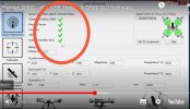
More specifically, you need to check if all the sensors are working, that is, if you get all the green ticks as from this image:
Screenshot_20220120_160752_com.android.chrome_edit_228754069753635.jpg
 
Last edited:
The use of the Gui is intuitive and very simple, in any case you can follow this video, it is in German but you can see how to do:
To view this content we will need your consent to set third party cookies.
For more detailed information, see our cookies page.

More specifically, you need to check if all the sensors are working, that is, if you get all the green ticks as from this image:
View attachment 27461
You are right...it is intuitive and I was actually to download and run the GUI program. It failed the "Orientation Sensor (IMU)"
and reason was: Accelerometer bias out of range. The other 4 have green check marks (Pressure sensor, Compass, GPS, and ESC.) I was also able to get all 4 motors to turn on by moving cursor over each motor at top-right of screen.
I then clicked on the "Calibration" Box and attempted to calibrate the Accelerometer, but got message it failed.

I stopped there because I need further guidance...please!
 
  • Like
Reactions: WTFDproject
You're in the same situation of the guys in this discussion:
Unfortunately the only way is to replace the IMU Chip (MPU6050) or the complete board.
 
  • Like
Reactions: WTFDproject
I've found this offer on internet, but I don't know this site and if it is serious.
For the price I would try...but it's up to you.... At your own risk

Personally I do not trust sites that do not provide their address and telephone contacts ... If you use a secure payment method, with a money-back guarantee in case of non-delivery of the piece, you can also try...
 
It looks like this problem is the same as the "Aquiring" problem that Typhoon H has. Q500 GUI seems to be better in diagnosis as the Hs GUI.

My question is: Did the ST10 also show a wrong altitude and/or slow rotation at Yaw in GUI?

br HE
 
You are right...it is intuitive and I was actually to download and run the GUI program. It failed the "Orientation Sensor (IMU)"
and reason was: Accelerometer bias out of range. The other 4 have green check marks (Pressure sensor, Compass, GPS, and ESC.) I was also able to get all 4 motors to turn on by moving cursor over each motor at top-right of screen.
I then clicked on the "Calibration" Box and attempted to calibrate the Accelerometer, but got message it failed.

I stopped there because I need further guidance...please!
ouch...not the news I wanted. I have limited soldering experience, so I don't think I can replace only the chip. I see that refurbished boards can be bought on line fo about $80. It looks like I will still need to solder the battery connector wires and the motor wires. How difficult is it to do this? Is there anything else I should know? It appears that the rest of the connections are plugs. Any advice is welcome & thanks to all who have helped thus far!
 
Just a suggestion,you could try a local radio,stereo tv,etc repair shop to do soldering for you. Best if you could just take them the items that directly need soldering.There are approx 70 screws give or take a few,to remove. I would call John at Yuneec skins in California. I have had him do 2 repairs for me. Both were perfect and reasonable. KC
 
  • Like
Reactions: Pier2162
Just a suggestion,you could try a local radio,stereo tv,etc repair shop to do soldering for you. Best if you could just take them the items that directly need soldering.There are approx 70 screws give or take a few,to remove. I would call John at Yuneec skins in California. I have had him do 2 repairs for me. Both were perfect and reasonable. KC
Great suggestions... and ...I see what you mean about all the screws! Never paid that much attention till now. Have taken mt 2 Typhoon H drones apart many times...much easier. Thanks !
 
  • Like
Reactions: 7cyclops
I've found this offer on internet, but I don't know this site and if it is serious.
For the price I would try...but it's up to you.... At your own risk

Personally I do not trust sites that do not provide their address and telephone contacts ... If you use a secure payment method, with a money-back guarantee in case of non-delivery of the piece, you can also try...
It does look a bit shady, but good price. Shipping would be $25 to me. Their "Contact Us" is a personal gmail address (?)
 
There are no feedbacks about that site, and no payments with PayPal... I would not trust to order...
**WARNING** Do not try to buy anything from that seller. I tried and it is a scam. Never got the main q500 board, but my credit card reimbursed me & I purchased another. On my original board, it was the largest chip (near center of board) that was damaged. Got another board and installed. Unfortunately I cracked one of the plug sockets on one of the ESCs. Motors won't start. Used GUI and sure enough...all tested good except the motor with the broken esc connector socket. Waiting for ESC now.
 
**WARNING** Do not try to buy anything from that seller. I tried and it is a scam. Never got the main q500 board, but my credit card reimbursed me & I purchased another. On my original board, it was the largest chip (near center of board) that was damaged. Got another board and installed. Unfortunately I cracked one of the plug sockets on one of the ESCs. Motors won't start. Used GUI and sure enough...all tested good except the motor with the broken esc connector socket. Waiting for ESC now.
Received and unstalled new ESC. Actually, it must have come from a drone since the 5 largest wires were cut. Tested drone with GUI and still getting error message for motor 1 that I just worked on. All other checkmarks are green and the other 3 motors will start. Waiting for replacement to arrive. Since job is a bit tedious I was wondering if anyone has any suggestions or words of wisdom.
 
Don't know if this helps but,,,I always wanted to try cut and splicing the wires that go to the esc. I would use a tight fitting bullet connector,,you know the pointy ones,that fit tight. Must be good as yuneec used these on the h480,. Either way good luck. Peace K.C.
 
Don't know if this helps but,,,I always wanted to try cut and splicing the wires that go to the esc. I would use a tight fitting bullet connector,,you know the pointy ones,that fit tight. Must be good as yuneec used these on the h480,. Either way good luck. Peace K.C.
There is not much room between motor & esc and connections are soldered. Wish they put the ESCs in main body like on the Typhoon H.
 
Received and unstalled new ESC. Actually, it must have come from a drone since the 5 largest wires were cut. Tested drone with GUI and still getting error message for motor 1 that I just worked on. All other checkmarks are green and the other 3 motors will start. Waiting for replacement to arrive. Since job is a bit tedious I was wondering if anyone has any suggestions or words of wisdom.
The one bit I would offer is that the three holes must be well cleaned of the old solder. The wires, and the residual solder in the wires, make a tight fit in the holes. The reduction in opening caused by any residual solder on the ESC holes becomes a problem. You can use several methods, like a solder sucker or desoldering braid, but the best results for me came from using some scrap wire coated in flux. You can stick the wire through the holes and pretty much get them clean as they were when you mounted them new.
 

New Posts

Members online

No members online now.

Forum statistics

Threads
21,146
Messages
243,803
Members
27,811
Latest member
estatedekho26