Hello Fellow Yuneec Pilot!
Join our free Yuneec community and remove this annoying banner!
Sign up

Q500 CG03: WiFi 30 feet range issue

Joined
Dec 31, 2021
Messages
9
Reaction score
4
Location
Adelaide Australia
Website
www.youtube.com
Hi all, I have Q500 4K with CGO 3 camera.
ST10+ and camera at latest firmware versions
All worked well prior to storage. No crash damage since it has been in my ownership
Camera stored on steady cam for probably 4 or 5 months.
Went to use just before Christmas and the 5.8GHz video range is about 10m/30 feet. All other features work (tilt/stabilisation/video and still capture)
  1. Placed camera on steady cam and used android phone same results wrt the video WIFI range
  2. Have created new profile and rebound both drone and camera to the ST10+, no effect to WIFI performance;
  3. Have re-seated the micro SD cards in both the camera and the ST10+ still not range improvement;
  4. Have checked the WIFI on a mobile phone WIFI monitor SSID is fine power is fine close in but drops rapidly with distance. Still have line of sight to theCGO3;
  5. Have looked at the clover leaf antenna it looks OK (tatty but OK), both the elements and where it attaches on the WIFI board;
  6. Have reset the WIFI (right button by the micro SD slot) no effect on video WIFI range; and
  7. Have looked at the WIFI board ribbon cable looks fine as do the two edge connectors.
Is there anything I have missed or anything else that I should try?
Would it be worth replacing the clover leaf antenna or go straight to a WIFI board replacement? Or is there another cause for this behaviour odd behaviour?

Thanks in advance for sharing your experiences/wisdom :)
 
Hi.
I suggest to try without sd card on the camera, sometimes bad cards can freeze wifi (happened on my Chroma..).
Don't use cards bigger than 16 Gb, and make sure they are high speed.
Check also antenna cable, plug, connector and welding of the ground side on the clover antenna.
Have you made calibration of the drone with the camera installed?
If so, the ribbon flat cable could be damaged (not easy to see if cracked).
 
Last edited:
the 5.8GHz video range is about 10m/30 feet.
  1. Have looked at the clover leaf antenna it looks OK (tatty but OK),
Would it be worth replacing the clover leaf antenna or go straight to a WIFI board replacement? Or is there another cause for this behaviour odd behaviour?
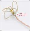
The mention of 10m/30feet is especially characteristic of antenna ground problems on the CGo3 series. It is not the only possible problem, of course, but it is a good first suspect. One of the common failure points of the CGo3 antenna is the solder joint mentioned by @Pier2162. If this solder joint is broken/weak/loose feeling, there is no connection to ground.
Antenna.jpg
If a camera is operated without a good antenna the WIFI board may suffer damage. You may wind up replacing the WIFI board anyway.
 
  • Like
Reactions: Pier2162
Hi.
I suggest to try without sd card on the camera, sometimes bad cards can freeze wifi (happened on my Chroma..).
Don't use cards bigger than 16 Gb, and make sure they are high speed.
Check also antenna cable, plug, connector and welding of the ground side on the clover antenna.
Have you made calibration of the drone with the camera installed?
If so, the ribbon flat cable could be damaged (not easy to see if cracked).
Hi Pier2162,

Thanks for the suggestions. It is late here so I have only been able to test the camera inside with no micro SD card. It may be giving me slightly better range, 5.8GHz doesn't really propagate well inside. But taking that as a positive I reformatted the micro SD card and reinserted it. The performance is the same as with no micro SD so will try it again tomorrow in free space. The card is a high speed one Class 10 U3 SanDisk, not to say it hasn't develop a whole load of bad sectors.
I did recalibrate the drone but for the life of me I cant remember if the camera was attached or if it was still on the steady cam. I did pay close attention to the ribbon cable when I looked inside and it appeared OK. Will see how we go.
 
WTFDProject; Firstly thanks for making the "Way To Fix Drones project" document available. It is an excellent resource and enabled me to have the 'quicklook' at the camera.

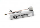
I will take the front cover off the camera and have a closer look at the antenna, as I said it looks tatty and with the picture you have provided I now have a better point of reference. I think that buying a replacement/second LHCP antenna might be a good investment before I fly again. I was already looking at the item below, would this TBS TRIUMPH PRO (LHCP U.FL) be a reasonable candidate?

1641035900777.png
Thanks again for the suggestion, I was thinking of biting the bullet and 'just' getting a replacement WIFI board. As you have highlighted if the antenna is broken/weak/loose I could destroy that as well. Experience is a wonderful thing :).
 
  • Like
Reactions: WTFDproject
I have been trying to get a definitive answer by searching the forums, but if somebody can confirm LHCP or RHCP for the CGO3 I would really appreciate it :). Fortunately (but annoyingly) nothing is open here in Australia till Tuesday so I have to wait before I can order an antenna.
 
I think it should not be so important, because the internal antenna of the ST10+ wifi receiver is a flat model antenna. Don't know if polarization is related to the wifi transmitter module type.
 
The Antenna in the ST10+ is flat, that could mean it is linear (H/V) but doesn't stop it being circular (L/R). I have read on the forums that it is LHCP but I don't know if this is fact or opinion. If it is linear you would lose 3dB with a circular antenna in the CGO3 (independent of whether it is V/H). The polarisation is not related to the transmitter module it is an artefact of the antenna. My antenna theory is very rusty which is why I would like confirmation but using the hand/thumb rule I think the clover leaf shown (both) is left, but as I said very rusty theory. If you are correct and the ST10+ is linear I am worrying over nothing.
 
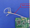
Here is an example of a bad clover leaf antenna. Note that the braided shield is separated from the solder joint at the bottom of the antenna.

21BCDC14-89BE-48F1-AACB-9C7BD2FDF98C.jpeg
 
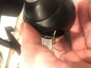
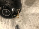
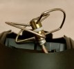
Thanks, that provides context of bad! I had already popped off the front cover so have attached a couple of quick photos, on first inspection it doesn't look too bad? Would value your opinion. I will need to disassemble to see the u.FL connector which I thought looked tatty. Let me know if better photos would be more helpful, I can retake in the morning and crop the excess and replace these snaps.

Antenna1.jpgAntenna2.jpg
 
The clover leaf end appears to be okay.
 
so have attached a couple of quick photos, on first inspection it doesn't look too bad?
It does not look obviously bad. Maybe not as clean at the end of the insulation as desired, but visual isn't the best.
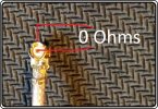
Check continuity between the center and the outer casing on the connector end. It should read as a dead short if the antenna joints are all making good contact.
Check.jpg

Please note continuity is also not conclusive. Checking continuity is only useful for detecting breaks in the circuit (open circuit). If the cable is shorted at the joint, at the connector (or anywhere else), the continuity will appear good but the signal will not be reaching the actual antenna lobes.
 
... on first inspection it doesn't look too bad?
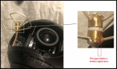
Oops. Missed this on the first look. Rotated and expanded, the picture shows an unexpected problem.
The signal wire is normally stretched tight between the top and bottom solder joints. The presence of this gap strongly implies the signal wire is broken and only the loops themselves are holding the antenna together.

Gap.jpg
 
Will measure later today, DoomMeister thanks for the link, the information confirms the hand/thumb rule that I use. I think the best course of action is to get a new antenna. I don't really want to do a full 'external antenna mod' as I still want to use the steady cam.
 
Oops. Missed this on the first look. Rotated and expanded, the picture shows an unexpected problem.
The signal wire is normally stretched tight between the top and bottom solder joints. The presence of this gap strongly implies the signal wire is broken and only the loops themselves are holding the antenna together.
Thanks for taking the time really appreciated. A new antenna is the way to go will remove all these unknowns. Then hope becomes the strategy i.e. hope the WIFI board is still fully functional.🤞

May I ask...... do you think that using an antenna like TBS TRIUMPH PRO mounted in the CGO would add additional strain on the gimbal mounts due to thw additional weight of the radome?? It weights in at 2-3g where a 'bare' clover leaf comes in at about 1.7g. The BETAFPV AIR 5.8GHZ DIGITAL VTX ANTENNA LHCP comes in at 1.09g. I have no experience of aftermarket antennas so any advice is better than a punt in the dark.
 
  • Like
Reactions: WTFDproject
..do you think that using an antenna like TBS TRIUMPH PRO mounted in the CGO would add additional strain on the gimbal mounts due to thw additional weight of the radome?? It weights in at 2-3g where a 'bare' clover leaf comes in at about 1.7g. The BETAFPV AIR 5.8GHZ DIGITAL VTX ANTENNA LHCP comes in at 1.09g. I have no experience of aftermarket antennas so any advice is better than a punt in the dark.
It would not add much strain on the mounts. But gimbal balance is more vulnerable.
I also don't have a lot of experience with using aftermarket antennas. The few attempts I made at chasing magic only led me to go back to the original antenna, mounted in the original manner. At best, the aftermarket miracles I chased did ALMOST as well as the OEM version. In one case an "unmentioned drawback" actually challenged the integrity of the gimbal due to so much additional mechanical burden.
 
  • Like
Reactions: bloggs_bill
Here is an example of a bad clover leaf antenna. Note that the braided shield is separated from the solder joint at the bottom of the antenna.

View attachment 27335
Just a note for those have soldering skills. I was able to repair this antenna. The center conductor was intact and the inner insulator was fine. I trimmed a bit of the outer insulation to expose more of the braided shield. I then wrapped some thin copper wire around the exposed shield and up to solder fillet at the base of the cloverleaf. I brushed a residue free active flux over the area then soldered the area quickly with a 720 deg F iron.
A86EF97A-7C5C-4C63-94D4-720243E59084.jpeg
 
Last edited:
  • Like
Reactions: WTFDproject

New Posts

Members online

No members online now.

Forum statistics

Threads
20,955
Messages
241,591
Members
27,287
Latest member
wccannabis