- Joined
- May 18, 2019
- Messages
- 42
- Reaction score
- 13
- Age
- 65
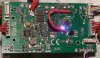
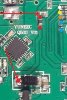
Think I found it I moved some of the main power wires to the side and noticed a burnt spot and seen a peace of solder or something so I cleaned it with alcohol a piece came off where the burnt spot was and this is what it looks like I'd say it's my board what do you think?Ok the ground on the main board reads continuity between the ground and the 4.6 lead then I checked for 4.6 V over to the black chip I get the 4.6 v but on the ground lead instead of red 4.6 on it I get 0.00 on red. I hope this makes sense. Sounds like the to are grounded over