Hello Fellow Yuneec Pilot!
Join our free Yuneec community and remove this annoying banner!
Sign up

Camera wires broke off circuit board

WOW, that is cheap for the repair. I fixed mine last night. I soldered all 3 wires back onto the cameras circuit board. I was going to rewire the whole harness and make it break away contacts to prevent this from repeating should I experience another "unfortunate event". It was late and I was tired so I took the lazy way out and just re-soldered them.

All in all it went pretty easy and only took me about 5 minutes after a 20 minute prep to dig out all my stuff to do it.

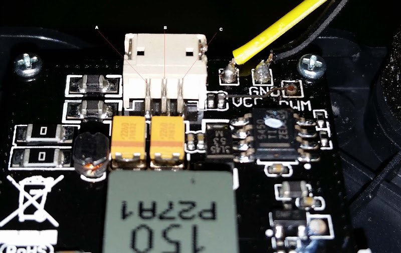
I did take the PWM lead and solder it to the back of the far right contact looking at the jack from the back. rather than the board because that would have required my rebuilding the ripped off trace that goes from the surface mount component over to the PWM pad.

I powered up the Q500 and tested the camera after the repair and it appears to be working fine. Today I took it out for live run and it worked flawlessly. I did not try it on the steadygrip, I don't have a device that is new enough to load the app. My cell phone I use as a phone, I TALK on it. :)

Still, 11.99 is a great deal if you don't have the tools, patience, or experience working with and soldering very small components. The camera and gimbal are too expensive to be taking chances with if your not comfortable doing it.

It was just out o the box and other damage to antenna cover and lens so I really wanted it thoroughly checked out. I had not seen any info on solder points for the wires till I found this forum.

I too have a phone, (Phonetic Device) used for talking! Got my wife's old S4 that I use on wifi only to see drone video. I did read that simultaneous viewing of cgo video will seriously slow it down by the way.
 
I did read that simultaneous viewing of cgo video will seriously slow it down by the way.

I can neither confirm nor deny that, but the logic does not make sense. The camera is sending out a constant signal in it's cone shaped direction. A second or third device receiving the signal should not cause any issues. It's another device trying to transmit on the same signal that may cause issues.
 
You wouldn't think so just for video, but as I understand it this is interactive and there is a feedback communication at play.
 
I can neither confirm nor deny that, but the logic does not make sense. The camera is sending out a constant signal in it's cone shaped direction. A second or third device receiving the signal should not cause any issues. It's another device trying to transmit on the same signal that may cause issues.

If more than one device could receive the transmitted video without transmitting back to the camera that would be fine. You could have 100 people watching the video. The problem is that if you are receiving you are also transmitting. The camera receiving from more than one "control point" simultaneously will slow it down.
 
Had my first crash with a 3 day old Q54K. The camera mount came apart and 3 wires disconnected from the mounts circuit board. And I couldn't find the rubber shock absorber. Dang it!

I emailed Yuneec and hope to hear something soon.

Just thought I'd share. This thing STILL rocks! Just user error.
View attachment 61


I have my first crash just now and same problem. Can you please help explain how i could fix it clearly. Did you order the board from Yuneec or you have it soled back?

Thanks!
 
I have my first crash just now and same problem. Can you please help explain how i could fix it clearly. Did you order the board from Yuneec or you have it soled back?

Thanks!
Hi Aldric,
I notice in your photo that you are using the harness that plugs into the back of the gimbal and underside of the Q500. Does your Q500 underside besides having the receptacle to plug the harness into also have 3 gold contacts where the gimbal slides on?

If you don't have the 3 contacts than you are not using the wires anyway. you could just tape the ends of the wires, coil them up, and not worry about it. If you have 3 contacts on the underside of the Q500 and you want to use this for your camera and not use the plug in harness you will need to re-solder the 3 wires to the board to re-connect the contacts on the gimbal's slide in mount to the circuit board.

If you are very good at soldering (if you're not don't attempt the repair yourself), have a small pencil type soldering iron, have decent eyesight, small very philips screwdriver, and patience not to rush the job it is not a hard project. You can do it yourself it only takes about 15 minutes. Other than the cost of a new set of shocks It won't cost you anything.

YUNEEC Rubber Dampers for CGO3-GB Camera (8-Pack)

if you are going to do the repair yourself I'll type you out some instructions. If you look at post #40 in this thread (you'll have to go back a couple of pages) it will give you some insight. This is an excellent post with photos. The 3rd photo down shows where the wires go. you will have to remove the cover from the gimbal contacts to make sure you are soldering the correct wire back on to the board. On mine I soldered 2 directly back to the board and like everyone else the 3rd wire "PWM" not only cam off the board but pulled part of a board trace with it. This can be re-soldered directly to the back off the harness connector. Holding the board so wire you soldered are on the right hand side of the connector the 3rd pin on the right is for the PWM circuit, look at the photos.

John O'
 
Last edited:
Thank You for the forum and all the advice and pictures, with solutions, Helped me so far, I'm repairing mine

Crashed mine last week, needs a complete rebuild, Does anyone know if the frame kit is complete, I have the assembly, coming Snail mail, I fractured the under carriage pretty bad, broke the wires, and I wish the plastic was more like a milk jug in flexibility , It almost seems like the stuff is office grade and just shatters. RC cars have a plastic shell that withstands impact well. Food for thought. As I post said , "does anyone not crash?" Thanks all
 
Last edited:
Ditto for me on the crash... after reading through the posts here, I figured I was in the clear to just rely on the pigtail connection, so I put the dampeners back together and powered on my Typhoon G. Within several seconds, the gimbal did not stabilize and I smelled smoke, then looked to see smoke coming from the area where the pigtail connects to the drone body. I have to call Yuneec support tomorrow. Really bummed - it was a silly crash.
 
Well, it was a good and bad day.

First off, the breakaway works as designed.

20160403_131957.jpg


20160403_132017.jpg


The bad part is that it got tested.

Hooked everything back up, and all is right with the world. Camera still works (second bounce test) and I was back in the air as soon as I put a pair of props on.

Cause of the crash appears to be a battery that has gone tango uniform. 5 minutes of flight on a fresh charge.

I really need to re-do mine and put a break-apart on it. Obviously the key here is to not test it :). But you never know. Do you use the Yuneec charger that came with it or a 3rd party charger where you have a display to show you whats going on? That's a bummer about the battery causing the unexpected landing.
 
Tenergy 5 amp charger. Been using it since Day one.

Batteries have been in storage charge since the end of January (broke my leg Feb 3) and have not flown until last week - finally able to move around and carry things. In about 3 hours I am going out again, and going to keep a real close eye on the batteries.

I still have not updated to the most recent ST10 firmware, just trying to get a good test of the Itelite mod that I did first.

I have not done a long range flight of this bird since January either - that was when I had a crash landing in a tree. Other than running figure 8's 100 feet away to kill the last 2 batteries before I came home, that was the last flight.

I may have something wrong internally on the original, so I have a NIB Q5004k sitting in the spare bedroom just in case this one is an organ donor.
 
OK...I did the ol' "Found a tree, knocked the gimbal off, broke the wires" thing. I was going to perform the repairs and put in a break away connection mid point in the leads from the gimbal mount to the gimbal so no more ripped wires off the circuit board the next time I crash.

So I finally got a hold of all the crap I needed to perform the repairs, and that one little inlaid wire that came loose from the circuit board, broke off. And everything was going so well too.

Getting ready to start.

20160209_193815.jpg


Finished the break away wires for the gimbal mount
20160210_025040.jpg


The inlaid wire and copper pad that ripped loose of the board.
20160201_131108.jpg


Got 2 of the lower wire soldered on, then that one that pulled the pad and wire loose from the board broke.
20160210_025242.jpg


SO - The current plan is to solder the PWM wire to the back of the pigtail connection port, but I need to know which lead is what.
Camera%252520board.jpg

Edited - Found the info - Thanks George for the tip
Left to right,
A ~ GND
B ~ VCC
C ~ PWM


So now that I found out which pin on the back of the connector I need to go to...

20160210_125226.jpg


Ran the wires under the board and up from behind, then through the cover.

20160210_125237.jpg


20160210_125332.jpg


Here is is all assembled and connected. The pins keep a good connection, and should pull free in the event of another gimbal mount separation. No I did not do a inertia test to verify. I will take it on faith that the solder joints and the wires will hold longer than the pins in the sockets.

Probably going to void the warranty on the other (yes, I bought a another Q500 set) and do this pre-emptively, so the board does not get damaged by ripping the solder joints out.

20160210_125759.jpg


I first tried to test in my steady grip, and everything was working, but the app. I then attached it to my Q and everything works as normal.

I had the same thing happens today and would like to do the same fix as you. Can you tell me the parts I will need (i.e. wire size and connector size and type).

Thanks
 
This is the wire that I bought.

http://www.amazon.com/Gikfun-Dupont...1&redirect=true&ref_=oh_aui_search_detailpage
I needed 3 pieces, and got 40. You could make your own or check with a local hobby shop (I lacked the time). So long as the wire is the same gauge as what you are replacing and the pin connectors do not have locking tabs, you should be good.

I want to say the pins on he connector type that I used were 2.5mm
 
Had my first crash with a 3 day old Q54K. The camera mount came apart and 3 wires disconnected from the mounts circuit board. And I couldn't find the rubber shock absorber. Dang it!

I emailed Yuneec and hope to hear something soon.

Just thought I'd share. This thing STILL rocks! Just user error.
View attachment 61
Had the same exact thing happen, and READ your explanation. Tucked the 3 black wires away and kept making great videos in 4K. You can see so many people threw questions out there, after you had already explained the wires weren't an issue, lol. My Q500 4k doesn''t even have the gold contact point mounts between the gimbal and body, so they aren't even used. My gimbal handgrip only has the plug too....no gold contact points.
 
Thanks for comprehending my explanation of my experience.
Glad it worked out for you. And remember, trees are closer than they appear! :D
 
OK...I did the ol' "Found a tree, knocked the gimbal off, broke the wires" thing. I was going to perform the repairs and put in a break away connection mid point in the leads from the gimbal mount to the gimbal so no more ripped wires off the circuit board the next time I crash.

So I finally got a hold of all the crap I needed to perform the repairs, and that one little inlaid wire that came loose from the circuit board, broke off. And everything was going so well too.

Getting ready to start.

Thank you!! This is exactly what I was needing but will probably look up Yuneec today to see if I can order/get those two parts but in the interim this is an excellent solution in case I can't.

What size wire did you use for this? My wife soldiered the two original wires back on last night but I would like to replace those wires with stronger ones like you did.

As a matter of fact, would you be willing to list the parts and part numbers you used?

Happy Flying!

David
New Q500 4K Owner
 
This is the wire assortment that I ordered from Amazon (had about 8 other things I needed)

http://www.amazon.com/Gikfun-Dupont...&redirect=true&ref_=oh_aui_detailpage_o00_s00

MalexMale MalexFemale FemalexFemale wires.

I just cut 3 Male x Female wires for what I did. The Double Male wires that came with the bunch I was able to use for making an adapter for my Micro quad batteries to hook up to my big charger.

Most of the connections on these RC units are all 2.5mm pins and sockets, so they will eventually be useful else where. If your local hobby shop can either make or sell the wires individually for less, that would at least save having to buy of the darn things when you only need 3, but at the time $8 delivered was a no brainer.
 

New Posts

Members online

No members online now.

Forum statistics

Threads
20,954
Messages
241,586
Members
27,284
Latest member
csandoval