

You are using an out of date browser. It may not display this or other websites correctly.
You should upgrade or use an alternative browser.
You should upgrade or use an alternative browser.
CG03+
- Thread starter markstopka
- Start date

Bit vague, was it a crash? Some more details if possible.Why & how do I stop the CG03+ from spinning ?

- Joined
- Nov 6, 2018
- Messages
- 1,103
- Reaction score
- 1,013
- Age
- 59
- Location
- DFW Metroplex
- Website
- orbisdroneservices.com
Many times there's unseen damage from a crash.....I'm sorry I can't help but there are others on here who can. Outside that, you'll have to send it in.....you've already got @WTFDproject 's attention so that's a good thing....
Does the calibration complete successfully? If so, do you reboot the aircraft right after the successful completion. It should then initialize a point straight forward.
Different cameras react a little different when things on the Gimbal Board are not connected to the right places. The general vision of "haywire" is certainly created if you get two or more of the motor connectors crossed. You did not mention which method you used to install the slip ring, so I will start with an assumption you unplugged gimbal board connectors and removed the gimbal board. If so, you need to ensure all connectors are in the right place. The drawing below will help with that. Note some newer cameras do not have the labels associated with the "special considerations" section of the drawing. If yours does not, please ignore this section of the drawing. If you do not find any errors in connectors, there will be a series of questions following the drawing that may help identify the issue. But first, please ensure all connectors are in order according to this drawing:

If all connectors are in the proper places, please help us identify the issue by answering these questions:
1.) Please clarify "haywire". You may not be referring to the same behavior. When a gimbal board has serious calibration issues, the camera goes into a state of erratic and constant twists, tilts, rolls, stalls and spins. Is this the behavior you see?
2.) If the "Haywire" phase is as described in question 1, at what point does it begin to Spin?
3,) Does the "Spin" include a continuation of the erratic movement?
4.) Please describe the spin. Is it at a steady rate? If so, is it fast, slow, somewhere in between?
5.)Does it always spin in the same direction? If so, does it spin left or right.
6.) When you run the gimbal calibration, does it appear to go through it's normal range of motion, and progress normally through the calibration?
7.) Does the camera behave the same on the steady grip as it does on the drone?
8.) Have you tried this camera on another drone?
9.) Have you tried another camera on this drone?
10.) Is there any difference in behavior with the controller on versus controller off?
11.) Are any beep codes sounding? If so, count how many long and how many short beeps you hear. If more than one code is involved, there will be a short pause between long/short sequence pairs.
12.) What method did you use to install the new slip ring? I.e..: Did you remove the gimbal board? Did you "fish" the wires out under the gimbal board? Did you use some other method?
13.) Have you checked to see if the Yaw Encoder is properly secured to the bottom side of the Gimbal Mount? If you replaced the slip ring wires by fishing them out of this area, this becomes a more significant question.
13.) What other damage was incurred during the crash?
14.) Are any wires on the original slip ring shorted to each other or to the metal ring housing?
- Joined
- Nov 6, 2018
- Messages
- 1,103
- Reaction score
- 1,013
- Age
- 59
- Location
- DFW Metroplex
- Website
- orbisdroneservices.com

h-elsner
Premium Pilot
- Joined
- Mar 23, 2016
- Messages
- 2,399
- Reaction score
- 2,161
- Location
- Bavaria / Germany
- Website
- h-elsner.mooo.com
15.) Is the ST16 powered on and is copter + cam correct bound? OK it is, otherwise calibration will not work.
16.) Did you check in HW-Monitor if S2 and K1 working correctly as expected.
17.) Check in Channelsettings if A06 is connected only to S2 and A04 only to K1.
br HE
16.) Did you check in HW-Monitor if S2 and K1 working correctly as expected.
17.) Check in Channelsettings if A06 is connected only to S2 and A04 only to K1.
br HE
Last edited:
- Joined
- Jan 6, 2016
- Messages
- 173
- Reaction score
- 53
- Age
- 70
I found the control to be very, very sensitive myself. when you think it's spot on. you notice the camera spin oh so gently. almost undetected. I've just learned to live with it.Why & how do I stop the CG03+ from spinning ?
PatR
Premium Pilot
I found the control to be very, very sensitive myself. when you think it's spot on. you notice the camera spin oh so gently. almost undetected. I've just learned to live with it.
During a recent activity where I disassembled an ST-16 and associated H-480 I found the gimbal on the aircraft was experiencing a very slow spin after reassembling the -16. Correction required cleaning pin connectors inside the ST-16 and spring contacts at the gimbal and aircraft.
Although not related to a slip ring repair, cleaning the gimbal contacts is something to try. I do not recommend disassembling an ST-16.
Last edited:
Different cameras react a little different when things on the Gimbal Board are not connected to the right places. The general vision of "haywire" is certainly created if you get two or more of the motor connectors crossed. You did not mention which method you used to install the slip ring, so I will start with an assumption you unplugged gimbal board connectors and removed the gimbal board. If so, you need to ensure all connectors are in the right place. The drawing below will help with that. Note some newer cameras do not have the labels associated with the "special considerations" section of the drawing. If yours does not, please ignore this section of the drawing. If you do not find any errors in connectors, there will be a series of questions following the drawing that may help identify the issue. But first, please ensure all connectors are in order according to this drawing:
View attachment 17628
If all connectors are in the proper places, please help us identify the issue by answering these questions:
1.) Please clarify "haywire". You may not be referring to the same behavior. When a gimbal board has serious calibration issues, the camera goes into a state of erratic and constant twists, tilts, rolls, stalls and spins. Is this the behavior you see?
2.) If the "Haywire" phase is as described in question 1, at what point does it begin to Spin?
3,) Does the "Spin" include a continuation of the erratic movement?
4.) Please describe the spin. Is it at a steady rate? If so, is it fast, slow, somewhere in between?
5.)Does it always spin in the same direction? If so, does it spin left or right.
6.) When you run the gimbal calibration, does it appear to go through it's normal range of motion, and progress normally through the calibration?
7.) Does the camera behave the same on the steady grip as it does on the drone?
8.) Have you tried this camera on another drone?
9.) Have you tried another camera on this drone?
10.) Is there any difference in behavior with the controller on versus controller off?
11.) Are any beep codes sounding? If so, count how many long and how many short beeps you hear. If more than one code is involved, there will be a short pause between long/short sequence pairs.
12.) What method did you use to install the new slip ring? I.e..: Did you remove the gimbal board? Did you "fish" the wires out under the gimbal board? Did you use some other method?
13.) Have you checked to see if the Yaw Encoder is properly secured to the bottom side of the Gimbal Mount? If you replaced the slip ring wires by fishing them out of this area, this becomes a more significant question.
13.) What other damage was incurred during the crash?
14.) Are any wires on the original slip ring shorted to each other or to the metal ring housing?
Thank you for the info. I will check my wiring again. the haywire is when I 1st turn The H on as it is powering up the gimbal starts to spin. And I think it is the same way , but will watch it & make a note of it. The way I gat it to stop is put it in cal mod & then it moves around till it is done. Thank you for your time
I found the trouble. gombal control board 1 of the pin sets came off, will have picture. Now need a new board. Any ideasDifferent cameras react a little different when things on the Gimbal Board are not connected to the right places. The general vision of "haywire" is certainly created if you get two or more of the motor connectors crossed. You did not mention which method you used to install the slip ring, so I will start with an assumption you unplugged gimbal board connectors and removed the gimbal board. If so, you need to ensure all connectors are in the right place. The drawing below will help with that. Note some newer cameras do not have the labels associated with the "special considerations" section of the drawing. If yours does not, please ignore this section of the drawing. If you do not find any errors in connectors, there will be a series of questions following the drawing that may help identify the issue. But first, please ensure all connectors are in order according to this drawing:
View attachment 17628
If all connectors are in the proper places, please help us identify the issue by answering these questions:
1.) Please clarify "haywire". You may not be referring to the same behavior. When a gimbal board has serious calibration issues, the camera goes into a state of erratic and constant twists, tilts, rolls, stalls and spins. Is this the behavior you see?
2.) If the "Haywire" phase is as described in question 1, at what point does it begin to Spin?
3,) Does the "Spin" include a continuation of the erratic movement?
4.) Please describe the spin. Is it at a steady rate? If so, is it fast, slow, somewhere in between?
5.)Does it always spin in the same direction? If so, does it spin left or right.
6.) When you run the gimbal calibration, does it appear to go through it's normal range of motion, and progress normally through the calibration?
7.) Does the camera behave the same on the steady grip as it does on the drone?
8.) Have you tried this camera on another drone?
9.) Have you tried another camera on this drone?
10.) Is there any difference in behavior with the controller on versus controller off?
11.) Are any beep codes sounding? If so, count how many long and how many short beeps you hear. If more than one code is involved, there will be a short pause between long/short sequence pairs.
12.) What method did you use to install the new slip ring? I.e..: Did you remove the gimbal board? Did you "fish" the wires out under the gimbal board? Did you use some other method?
13.) Have you checked to see if the Yaw Encoder is properly secured to the bottom side of the Gimbal Mount? If you replaced the slip ring wires by fishing them out of this area, this becomes a more significant question.
13.) What other damage was incurred during the crash?
14.) Are any wires on the original slip ring shorted to each other or to the metal ring housing?
Attachments
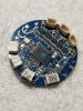

I found the trouble. gombal control board 1 of the pin sets came off, will have picture. Now need a new board. Any ideas
Attachments
New gimbal boards are expensive, and will have to be sent for calibration at a service center.
The good news is these connectors can be soldered back on without too much trouble. If you aren't familiar with soldering small things, a local computer/radio repair shop might be able to help you out a lot faster and a lot less expense.
I broke one off ("F" in the drawing above) while I was researching your problem. Just soldered it back on and kept going.
The bad news, is that I don't think that is your problem. That connector is the Camera IMU. Had it been broken off earlier, You would have heard a series of beep codes, and the camera would have failed to initialize.
Need help with CGO3+ Camera after replacing main gimbal control board
I recently got my hands on a Typhoon H Drone from a friend. According to said friend, the drone itself works fine but the camera had issues. The main problem was it would not tilt up or down but could pan left and right just fine. I already checked the ST16 to make sure all the controls...
 yuneecpilots.com
Similar threads
- Replies
- 1
- Views
- 262
- Replies
- 26
- Views
- 2K
- Replies
- 3
- Views
- 570
- Replies
- 11
- Views
- 543