Sounds like no communication. Thoughts:
If you were already using the same controller and USB, and since you have already tried the camera on a known good drone, then we are back to the assumption the issue is in the camera.
If the communication issue is in the camera, the purpose of the USB cord becomes important. It means we do not know whether the failure is created by the USB related circuit or by the SD card related circuit. A well-equipped factory backed shop could do better analysis. The x-mount will make connection to @h-elsner's calibration GUI impossible unless the actual drone will work as a calibration stand. I have no idea if that will work without destroying the H520e (a really "not good" idea unless someone knows something).
At our level, you will likely need to start swapping parts or mix/matching the major unit sections to find the issue.
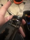
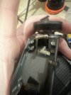
The x-mount down to the gimbal board might be easier to swap, but unless someone can tell us what the USB cord does, it might not even be a player in the update process.
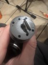
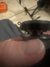
Splitting the camera at either the roll joint or the pitch joint would be next. In either case the lack of calibration will cause violent, erratic movement of the camera unless you control it with your hand until the update takes over and after the update finishes.
I did not find any update instruction in either the H520e-RTK manual or online. If you can post the steps you are following it would be great.
- I have no idea what the required baud rate is, but since the same file worked on other cameras, it is probably correct.
- I also have no idea what role the USB cord plays. I have no idea if anything in that circuit, either drone end or controller end could be at fault. If the same controller and USB cable were used for the successful updates, it would pretty well rule out those. (if not, try one of the sets that worked).
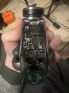
- The camera is at least reading and writing to the SD card well enough to create the log file. That downplays the likelihood of a bad SD card slot.
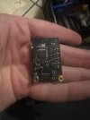
- The gimbal board has some function, albeit not normal. That also downplays (but does not rule out) the gimbal board.
If you were already using the same controller and USB, and since you have already tried the camera on a known good drone, then we are back to the assumption the issue is in the camera.
If the communication issue is in the camera, the purpose of the USB cord becomes important. It means we do not know whether the failure is created by the USB related circuit or by the SD card related circuit. A well-equipped factory backed shop could do better analysis. The x-mount will make connection to @h-elsner's calibration GUI impossible unless the actual drone will work as a calibration stand. I have no idea if that will work without destroying the H520e (a really "not good" idea unless someone knows something).
At our level, you will likely need to start swapping parts or mix/matching the major unit sections to find the issue.
The x-mount down to the gimbal board might be easier to swap, but unless someone can tell us what the USB cord does, it might not even be a player in the update process.
Splitting the camera at either the roll joint or the pitch joint would be next. In either case the lack of calibration will cause violent, erratic movement of the camera unless you control it with your hand until the update takes over and after the update finishes.
I did not find any update instruction in either the H520e-RTK manual or online. If you can post the steps you are following it would be great.

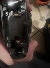
 . From taking apart the e10t and how delicate things are in these units I’m being a bit more cautious this time . My score sheet after these kind of things most often looks like this , electronics 1, me 0 , ziplock bags 5