- Joined
- Mar 22, 2020
- Messages
- 134
- Reaction score
- 67
A member I talked with the other day, I forget his SN off hand, but kudos goes to him for the idea, I just had the resources to execute it... Let me say it was a good idea and even a great result of the fix in general, but the flex-ability of plastics at this thickness required for the part just is not the fix We were hoping for. Figured I would post it where the rest of you could weigh in..
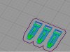
His Idea was to 3D print a new Leg spring lock Latch.... (I know right! Great Idea)
I have measured and 3D modeled one of almost exact dimensions, and It printed excellent as usual")
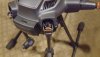
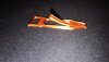
Installed just as excellent, the overall fit was right on the money that when I folded the arm up to catch the lock, I heard it click into place like the original. But this is where the excitement stops. When I folded the arm back in the down position the printed clip just bent and flexed in a bowing arch while still latched to the inner hook on the main body.
So to sum up, I loved the idea, I executed the idea w/ an excellent finish and fit. But in the end it just was not thick enough to get a solid hold on the arm assembly to support the needed weight.
In theory it did work and was even achievable in designing. But the slim fitting location just does not allow it to go any thicker.
Cad modeled in - A cheap free 2D modeling program my friend sent me
- And was imported into Solidworks for fine tuning the arcs and splines.
Sliced in - Simplify3D
Printed on - Ender 5Plus w/glass print bed and highly modified Print head.
With - Silk orange Pla+ filament W/ temps of 212C for hetend, and 70C for print bed.
Ok Boys let the death by a thousand cuts begin.
I took a video of the install and test, but it got to 80% uploaded and was unsuccessful
His Idea was to 3D print a new Leg spring lock Latch.... (I know right! Great Idea)
I have measured and 3D modeled one of almost exact dimensions, and It printed excellent as usual
Installed just as excellent, the overall fit was right on the money that when I folded the arm up to catch the lock, I heard it click into place like the original. But this is where the excitement stops. When I folded the arm back in the down position the printed clip just bent and flexed in a bowing arch while still latched to the inner hook on the main body.
So to sum up, I loved the idea, I executed the idea w/ an excellent finish and fit. But in the end it just was not thick enough to get a solid hold on the arm assembly to support the needed weight.
In theory it did work and was even achievable in designing. But the slim fitting location just does not allow it to go any thicker.
Cad modeled in - A cheap free 2D modeling program my friend sent me
- And was imported into Solidworks for fine tuning the arcs and splines.
Sliced in - Simplify3D
Printed on - Ender 5Plus w/glass print bed and highly modified Print head.
With - Silk orange Pla+ filament W/ temps of 212C for hetend, and 70C for print bed.
Ok Boys let the death by a thousand cuts begin.
I took a video of the install and test, but it got to 80% uploaded and was unsuccessful
Attachments
Last edited: