Given that I took the h520e rtk to do surveys and not as a tester like for autel evo, it is clear that I will do some tests to understand how to exploit its full potential, but this does not dispense yuneec from criticism for an attitude of complete absence of answers for its customers. Having said that, for now I have carried out several flights in rtk and I am at first evaluating the reliability of this method which, anyway, reports a series of anomalies that I am evaluatingYes, the Evo II Pro RTK will have 6K video capability but only at 30p and the image sensor is the same as the H520E RTK.
The EVO is available pretty much everywhere "as a test" but they are now 6 months behind in delivery so obviously they haven't gotten it all figured out yet. Oh and where exactly does Autel state the positional accuracy of the unit in flight? They don't... only the hovering.
As I have said multiple times we all understand that there are a lack of instructions for the PPK processing on the H520E RTK. It's pretty obvious what is on the mSD card so why don't you state what specifically you are having trouble understanding? It would be much more helpful to troubleshoot the process than continuing to wail about the lack of support on a user forum expecting a corporate answer. My personal opinion is that if you are not willing to dig in and help us all figure out the best PPK workflow then you are probably one of those individuals that should just stick with the ease of the RTK.


You are using an out of date browser. It may not display this or other websites correctly.
You should upgrade or use an alternative browser.
You should upgrade or use an alternative browser.
H520E RTK help
- Thread starter ermaITA
- Start date
this is a capture of the .txt file that is generated in the dcim folder of the photos, what does it correspond to??Yes, the Evo II Pro RTK will have 6K video capability but only at 30p and the image sensor is the same as the H520E RTK.
The EVO is available pretty much everywhere "as a test" but they are now 6 months behind in delivery so obviously they haven't gotten it all figured out yet. Oh and where exactly does Autel state the positional accuracy of the unit in flight? They don't... only the hovering.
As I have said multiple times we all understand that there are a lack of instructions for the PPK processing on the H520E RTK. It's pretty obvious what is on the mSD card so why don't you state what specifically you are having trouble understanding? It would be much more helpful to troubleshoot the process than continuing to wail about the lack of support on a user forum expecting a corporate answer. My personal opinion is that if you are not willing to dig in and help us all figure out the best PPK workflow then you are probably one of those individuals that should just stick with the ease of the RTK.
Attachments
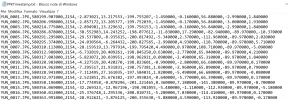
This is the same data that is in the RTK values of the images. If you turn off RTK on the ST16 you would use this file to replace the exif data as it coordinates with the GPS track. The second and third columns are the GPS seconds and the GPS week giving you the precise location on that track.this is a capture of the .txt file that is generated in the dcim folder of the photos, what does it correspond to??
it is different from the file that generates the ph4, I do not understand some columns what they are... and there's no starting line of referenceThis is the same data that is in the RTK values of the images. If you turn off RTK on the ST16 you would use this file to replace the exif data as it coordinates with the GPS track. The second and third columns are the GPS seconds and the GPS week giving you the precise location on that track.
Attachments
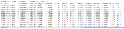
If you look at the exit data in exiftool or the version of exiftool in geosetter you will figure out what the columns are. They include items like the yaw of the drone and the gimbal and the pitch of each as well.it is different from the file that generates the ph4, I do not understand some columns what they are... and there's no starting line of reference
unfortunately all this information is not thereIf you look at the exit data in exiftool or the version of exiftool in geosetter you will figure out what the columns are. They include items like the yaw of the drone and the gimbal and the pitch of each as well.
Attachments
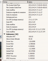
I see it in my Geosetter.unfortunately all this information is not there


you're right I downloaded geosetter and I see a lot of info but strangely the metashape doesn't matter to me...anyway thank you
Attachments
I have processed a survey about 2.5km long and 150m wide and I have errors contained within 10cm, only on the z I have errors equal to the distance between camera and antenna (30cm), so it is not corrected by softwareI have a simple question: has anyone managed to build a cloud (RTK accuracy) based only on telemetry data?
I don't understand the specifics of your question but we have now processed 14 maps and have found that in our use-case as was with the Phantom 4 RTK that GCP's are required. Processed without GCP's and using a single-point calibration is yielding results in the order of +/- 5cm XY and 7cm Z. So far we can say that the P4RTK was a little better but not really worth noting. We require GCP's because of the nature of construction control networks and with the GCP's we are seeing 2-3cm checkpoints in XY and Z. The interesting thing is that the RMSE's of the GPS camera locations have had a Z-value better than the XY which is usually not the case.I have a simple question: has anyone managed to build a cloud (RTK accuracy) based only on telemetry data?
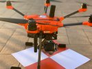
then it's great. I also use gcp and rtk, in truth I have the h520e rtk by little time even though I'm doing some surveys now and I have noticed two things that leave me perplexed, the first is that the z has a systematic error of about 30cm, and so I thought that it had not been considered there the offset of the antenna and another thing is that the values of pitch, roll and yaw save them only on the jpeg and not on the dng (which instead I use after having improved it) and that the metashape pro (1.5.1) does not see them, and instead they would be very important for the internal orientation of imagesI don't understand the specifics of your question but we have now processed 14 maps and have found that in our use-case as was with the Phantom 4 RTK that GCP's are required. Processed without GCP's and using a single-point calibration is yielding results in the order of +/- 5cm XY and 7cm Z. So far we can say that the P4RTK was a little better but not really worth noting. We require GCP's because of the nature of construction control networks and with the GCP's we are seeing 2-3cm checkpoints in XY and Z. The interesting thing is that the RMSE's of the GPS camera locations have had a Z-value better than the XY which is usually not the case.
Is it always "exactly" 30cm? Can you set the done on a GCP and check? The offset from the sensor to the ground is 7.5cm and the sensor to phase center of the antenna is about 21cm. Sorry but we have not seen this so I'm not much help.then it's great. I also use gcp and rtk, in truth I have the h520e rtk by little time even though I'm doing some surveys now and I have noticed two things that leave me perplexed, the first is that the z has a systematic error of about 30cm, and so I thought that it had not been considered there the offset of the antenna and another thing is that the values of pitch, roll and yaw save them only on the jpeg and not on the dng (which instead I use after having improved it) and that the metashape pro (1.5.1) does not see them, and instead they would be very important for the internal orientation of images
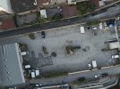
one of the tests I performed is to hit a point on the ground and on the same point detect the coordinates of the photo taken in rtk and the error was about 32cm, which is the same error that I have when processing with the gcpIs it always "exactly" 30cm? Can you set the done on a GCP and check? The offset from the sensor to the ground is 7.5cm and the sensor to phase center of the antenna is about 21cm. Sorry but we have not seen this so I'm not much help.
Attachments
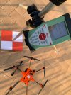
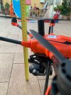
Surely an odd problem. I just doublechecked the specs on the OEM antenna and it is actually 20cm from the sensor to the phase center of the antenna but there is a little wiggle in that because L1 and L2 are slightly offset but only about +/- 1.5mm. Are you using a local base or RTK via NTRIP?one of the tests I performed is to hit a point on the ground and on the same point detect the coordinates of the photo taken in rtk and the error was about 32cm, which is the same error that I have when processing with the gcp
RTK via NTRIP, sorry but do you have any updated manual on rtk more than 20210203? because I have not found this information of 21cm anywhere ... I actually read somewhere in L1 and L2 on top of each other but now I can't find where, in any case the manuals are very lackingSurely an odd problem. I just doublechecked the specs on the OEM antenna and it is actually 20cm from the sensor to the phase center of the antenna but there is a little wiggle in that because L1 and L2 are slightly offset but only about +/- 1.5mm. Are you using a local base or RTK via NTRIP?
Last edited:
That's a newer manual than I have been able to find. I had to measure everything with a laser level. If you look on the bottom of the antenna it will tell you the pc for L1 and L2 at 29mm and 32mm respectively. Without their exact specifications it will be hard to verify cm-level accuracy but your 30cm is obviously a bust in measurement somewhere. I assume you are using the NTRIP for your rover as well? What is the provider casting? Maybe there are different datum between the rover and the drone?RTK via NTRIP, sorry but do you have any updated manual on rtk more than 20210203? because I have not found this information of 21cm anywhere ... the manuals are very lacking
Would you mind sharing that manual?
I use HxGN SmartNet with etrf2000, which other datum has 30cm difference in z?That's a newer manual than I have been able to find. I had to measure everything with a laser level. If you look on the bottom of the antenna it will tell you the pc for L1 and L2 at 29mm and 32mm respectively. Without their exact specifications it will be hard to verify cm-level accuracy but your 30cm is obviously a bust in measurement somewhere. I assume you are using the NTRIP for your rover as well? What is the provider casting? Maybe there are different datum between the rover and the drone?
Would you mind sharing that manual?
I don't know but ETRF2000 is a horizontal datum right?I use HxGN SmartNet with etrf2000, which other datum has 30cm difference in z?
Is a dinamic european WGS84I don't know but ETRF2000 is a horizontal datum right?
Similar threads
- Replies
- 33
- Views
- 4K
- Replies
- 10
- Views
- 2K
- Replies
- 7
- Views
- 2K
- Replies
- 2
- Views
- 2K
