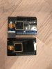
I have prepared my MCU board for flashing with small socket connectors. Matching pins come from legacy electronic parts like resistors.
Programmer board was ordered. Beginning next year I'm ready to flash (or finally burn) my spare MCU...
I'm really curious about that.
br HE
Looking good! Unless you shorted something out while soldering, burning your MCU board using the SWD would be quite a stunt. Please take care of ESD precautions, however, while handling the board and the open drone. ;-)
There are two jumpers on the Nucleo board, near the SWD header. When they are in place, the ST-Link flashes the Nucleo's F7. If they are removed, the ST-Link flashes whatever is connected to the header. Remove the jumpers and connect the board to the computer. There are two USB connectors, one is on the ST-Link (that removable part of the board) side, another one is on the opposite side. This is USB OTG for the F7. What is good to know, that there is a warning in the manual that the board does not like to powered from this. Use the ST-Link's connector.
Install the STM32 ST-Link utility, it is available here:
https://www.st.com/en/development-tools/stsw-link004.html
Manual:
https://www.st.com/content/ccc/reso...df/jcr:content/translations/en.CD00262073.pdf
Go to Target -> Connect to verify that the MCU is connected. If not, check the wiring. Set RDP protection to level 0 on Target -> Option Bytes. RDP Level 0 = No protection. 1 = Memory Readout Protection (you can not read back data from the Flash: Yuneec's bootloader and application), 2 = Memory protected, debug disabled AND this is permanent = do not set this one. Going from 1 to 0 erases everything, and there is no going back from here.
Go to Target -> Program & Verify. In my binary zip,
tonirosendahl/Thunderbird , there is "omnibusf4sd_bl.bin". Flash this to the MCU. This is a bootloader from OmnibusF4SD board, that has CGO3+ PWM initialization pulse added in my lazy and ugly way. ;-) When the CGO3+ serial communication gets resolved, this init pulse is no needed and an unmodified bootloader could probably be used. But until then, no ST-Link is needed from now on.
The MCU has now a PX4 bootloader, placed in the beginning of the Flash, 0x8000000. This is where the ROM bootloader starts up, whatever there is. There is no way to brick the STM32, the ROM bootloader will always be there, and the bootloader you just flashed, is a "second stage" bootloader, which is started by the ROM bootloader. The MCU or the ROM bootloader does not actually care what is placed into 0x8000000, whatever there is, gets started.
The actual PX4 firmware is compiled and linked so, that it starts from 0x8008000. That gives some space to save parameters, between the bootloader and the PX4 main application. The linker script, if interested, is at Thunderbird/boards/yuneec/typhoon_h/nuttx-config/scripts/script.ld but you should not need to modify it. If you want to ditch the PX4 bootloader and save parameters on a SD-card, then this is the place to modify the PX4 to start from 0x8000000. But for now, do not modify anything there. ;-).
Now, there are two ways to flash the main application.
A) The bootloader way: The PX4 bootloader you just flashed, is capable of flashing the main application via Typhoon's USB and then start it, from address 0x800
8000. No need to use the ST-Link any more; you can close the drone's lid. The bootloader has few seconds delay for flashing. The flashing is done using a slightly modified px_uploader.py script. Clone my repository to get these. This script requires the .bin file to be converted to .fw file (also in the zip) after compiling. See the "flash_typhoon_bootloader.py" script, write your COM port there, and while the script is running, connect the Typhoon to your computer. I do my development in Ubuntu 16.04 LTS, I don't know how this works in Windows, I'll write soon how to setup a nice development environment, too. ;-) However, if this gives you issues, there is also...
B) The ST-Util way (aka "my python scripts suck" -way) ;-). Flash the "yuneec_typhoon_h.bin" to the MCU, the same way you flashed the bootloader, but this time, starting from 0x800
8000. Done. ;-)
Reboot the drone. The drone's power button has a delay of ~8 seconds. During those, the button must be kept pressed. When all lights illuminate, release the power button. The drone is turned off by removing the battery.
Install the QGroundcontrol. Power up the drone. Connect the USB. Load my parameter file using QGC's parameter page. Re-calibrate sensors and radio, probably voltage divider. Verify my settings (Flight modes especially). Go flying. ;-)
Troubleshooting:
-If the drone does not appear as an USB device when the USB is connected AND the drone is powered off: Well, all is lost now. You are having a bootloader flashing issue OR the main autopilot firmware got accidentally flashed to 0x8000000. Re-flash everything and it will be fine. ;-)
-If the drone appears as an USB device but it does not start after a long press of the power button: The main firmware flashing went wrong. Re-flash, starting from 0x800
8000


")


.jpg")

