So here it goes what I found saved on my computer about Yuneec protocols.
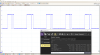
(well... the growing PWM ramp actually doesn't exist - I'm getting older )
)
Probably you found them already, but just in case...
Gimbal signaling :
 www.kopterforum.de
 www.rcgroups.com
SR24 zigbee protocol, files attached (only for Q500 and without telemetry ...):
 yuneecpilots.com
I played a little with the Typhoon H motherboard with stock firmware and I managed to lift it in the air (sort of...) with custom arms and custom motors+props, but due to the inability to tune it I gave it up for the moment.
Initially I wanted to port it to INAV, but my coding skills are close to zero, so even if I able to do the port definitions, I can't compile it (beeing an electrical engineer). Anyhow, INAV doesn't compare to AP/PX4, at least for cinematographic platforms...
Once I wanted to do it to the Phantom3 (having a F427, it would be a good pretender to AP or PX4)") , but the H is much easier to port to AP/PX4.
, but the H is much easier to port to AP/PX4.
As a side-note, I found a creepy similarity between the CGO3 and CGO3+ gimbal controllers' hardware and the 32bit version of AlexMos boards. But the research ends here, because they are closed source ones and each of them is somewhat activated and tracked by their S/N.
Keep us tuned and best regards,
Zsolt
Edit:
The big hexa is using the stock ESC board? I checked it's power capability and concluded that they are waaay oversized, but no way till 3508-sized motors on 15"
I tested it initially with 2216-810kV on Phantom2 props (9,5"x4,5") but wanted to upgrade to 10"x5" or 11"x5" props, still on the safe side IMHO...
(well... the growing PWM ramp actually doesn't exist - I'm getting older
)Probably you found them already, but just in case...
Gimbal signaling :
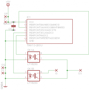
Horizon CGO2 mit Standard Empfänger schwenken. - Sonstige Tutorials - Tutorials
Die CGO2 lässt sich nicht von einem normalen Empfänger ansteuern der ein Signal im Bereich 1000us - 2000us sendet.Hier eine kleine Selbstbaulösung.
Using CGO2 with standard PWM receiver - Page 3 - RC Groups
Page 3-Mini-HowTo Using CGO2 with standard PWM receiver R/C Blogs
SR24 zigbee protocol, files attached (only for Q500 and without telemetry ...):
Typhoon H / ST-16 controller : Can it be re-purposed?
Just trying to understand some of this post ( way out of my league) what I am trying to find out if I could put a Yuneec flight controller in a 550s frame and run it with the ST16 ???? I think there is a little more to it than that. I'm pretty sure that in addition to the the yuneec flight...
yuneecpilots.com
I played a little with the Typhoon H motherboard with stock firmware and I managed to lift it in the air (sort of...) with custom arms and custom motors+props, but due to the inability to tune it I gave it up for the moment.
Initially I wanted to port it to INAV, but my coding skills are close to zero, so even if I able to do the port definitions, I can't compile it (beeing an electrical engineer). Anyhow, INAV doesn't compare to AP/PX4, at least for cinematographic platforms...
Once I wanted to do it to the Phantom3 (having a F427, it would be a good pretender to AP or PX4)
, but the H is much easier to port to AP/PX4.As a side-note, I found a creepy similarity between the CGO3 and CGO3+ gimbal controllers' hardware and the 32bit version of AlexMos boards
. But the research ends here, because they are closed source ones and each of them is somewhat activated and tracked by their S/N.Keep us tuned and best regards,
Zsolt
Edit:
The big hexa is using the stock ESC board? I checked it's power capability and concluded that they are waaay oversized, but no way till 3508-sized motors on 15"
I tested it initially with 2216-810kV on Phantom2 props (9,5"x4,5") but wanted to upgrade to 10"x5" or 11"x5" props, still on the safe side IMHO...
Attachments
Last edited:
") (The gimbal has a Sony 10X analog low-res/high-speed camera core, Storm32 gimbal controller, mechanics and yuneec -> ppm/visca converter designed and 3d-printed by me). It could be a bit too heavy for the Typhoons. The big hexa has a Pixhawk 2.1 and separate ESCs; no Yuneec hardware there except the Mk58 video transmitter and SR24 receiver ;-) The Typhoon's ESCs are indeed not suitable for that kind of motors.
(The gimbal has a Sony 10X analog low-res/high-speed camera core, Storm32 gimbal controller, mechanics and yuneec -> ppm/visca converter designed and 3d-printed by me). It could be a bit too heavy for the Typhoons. The big hexa has a Pixhawk 2.1 and separate ESCs; no Yuneec hardware there except the Mk58 video transmitter and SR24 receiver ;-) The Typhoon's ESCs are indeed not suitable for that kind of motors.
 I think I will wait till the "official" release