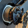
Hello Fellow Yuneec Pilot!
Join our free Yuneec community and remove this annoying banner!
Sign up

CGO3+ gimbal pitch tilt limited to narrow range

SAJ

Joined
Sep 14, 2022
Messages
6
Reaction score
4
Age
63
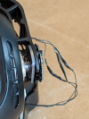
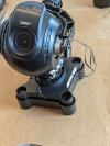
During the most recent flight of my Yuneec Typhoon H with CGO3+, I flew a tad too low over a roof and clipped the bottom of the camera on the top of the roof ridge. No crash, but the event force rotated the camera in the gimbal such that it was jammed 90 degrees on the roll axis, and broke the mount (in a typical way) at the spin plate. The drone continued to fly and the camera continued to function, but the gimbal was a mess.

Unwisely, I attempted to force the camera back into position before careful inspection. I am unsure of the crash did this, or my 'field adjustment', but the result of all of this was the three wires that connected to the pitch servo motor were severed. (This was the impetus for resurrecting my rusty micro-soldering skills.)

Recovery and repair included reassembling with epoxy the mount plate, soldering and electrically insulating (with liquid tape) the motor connecting wires, and reassembly to test operations on the table with the ST16. (Otherwise, if the repair fails I am probably looking at buying a replacement camera/gimbal set.)

Post repair status:
  • The camera functions, transmits to ST16. status light on the camera is green, and the ST16 does not report an initialization error (as long as I have a memory card installed in the CGO3+).
  • The gimbal mechanically has full articulation without noticeable binding, however....
  • The gimbal has full yaw control, but pitch is limited to about 15-20 degree arc. That is, I can use the ST16 to fully rotate the horizontal direction of the camera, but the up/down angle is limited to a narrow arc. I can manually adjust downward or upward and it will hold the position, but the ST16 control does not direct the up/down more that its limited arc.
  • The stability functions seem to function within the short-arc limits of the tilt. Roll works perfectly, and yaw is smooth, but the automatic stability adjustments on the pitch axis are limited to the short arc.
  • I attempted to calibrate the gimbal from the ST16. The CGO3+ board LED signals red/green. This went on for a while but never seemed to complete. Turning off the Typhoon H and back on seemed to reset the calibration, and the LED signals green (as before).
  • Starting up the drone seems normal: No visual or audible error codes are thrown. The camera resets to a normal looking orientation from its limp off state, but pitch control is low or non-existent.
  • I checked the wire continuity of the pitch sensor, just in case that wire was damaged in the incident - wires are good from end-to-end. I have not tested the repaired motor wire (yet) because it is difficult to get to the motor side of the bare wire. (I would need to peel back the insulation to confirm the solder repair was good.)
I have not yet flight tested this, but do not expect that the gimbal will act any differently in flight than on the table. I am reasonably sure the wires on not crossed because the movement of the motor is in the correct direction of the instructions from the ST16. I suppose the software could somehow compensate in a limited way if I reversed the power. Thoughts?

Does anyone have an idea on what is going on here? Everything works, except the range of tilt is very limited. I had to reconnect the wires, so it is possible they aren't correct, or have inadequate continuity.

Help please!
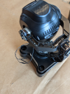
1663269019450.png 1663269037391.png1663269082587.png
 
Last edited:
During the most recent flight of my Yuneec
Typhoon H with CGO3+
, I flew a tad too low over a roof and clipped the bottom of the camera on the top of the roof ridge. .......
Help please!
There is a lot to take in here. The real answer is the camera should be sent in for a repair.
But there are a couple of things you can check at home first:
1.) Motor damage: Does the pitch motor have any "catches" when you move it by hand?
2.) Bent arms: Bent arms are hard to detect and a three-dimensional nightmare to correct. The common symptom is the pitch will have one (or sometimes two) "positions" it wants to hold and will spring back into that position when released. (Hence the term "Pitch Spring".)
3.) Crossed wires: You may be able to unlatch the wires at the gimbal board connector and swap them around to experiment. Many connectors have too much glue, but some will unlatch and come out. It can get confusing if you don't do something to mark the original position of the wires. Edit: Also see CGo3+ Roll and Pitch Encoder Pinout.pdf as required.
4.) Gimbal board damage: That's gonna be a shop diagnostic/repair if there is no obvious damage.
 
Last edited:
Thank you for your reply. I am checking into authorized repair, but want to complete these home checks. Here is what I have:

Motor damage: unlikely - the motor has no catches, and can be smoothly rotated by hand
Bent arms: unlikely - no unusual spring or hold positions; visually looks straight
Crossed wires: unknown/TBD - I still need to swap wires and test (see below)
Ginbal board damage: doubtful, as there is no visible trauma, and the startup diagnostics report all as normal. (no errors)

Can you point me to a video that demonstrates the procedure for extracting the pins from the connector? Much appreciated.
 
.......
Can you point me to a video that demonstrates the procedure for extracting the pins from the connector? Much appreciated.
It would be a good idea to check the pitch magnet as suggested by @Vaklin. Some examples of degradation are shown in the first PDF image below. In the early stages of degradation, the magnet may look perfectly normal, but have less magnetism. It can be compared to the roll magnet for a general idea of how strong it is.

The connector is a JST type similar to the second PDF below. If the adhesive puddled on the wires can be removed, it is just a matter of lifting each latch as shown in the PDF.
 

Attachments

  • Examples.pdf
    552 KB · Views: 29
  • Release Pin Latches.pdf
    302.6 KB · Views: 28
  • Like
Reactions: DoomMeister
It would be a good idea to check the pitch magnet as suggested by @Vaklin. Some examples of degradation are shown in the first PDF image below. In the early stages of degradation, the magnet may look perfectly normal, but have less magnetism. It can be compared to the roll magnet for a general idea of how strong it is.

The connector is a JST type similar to the second PDF below. If the adhesive puddled on the wires can be removed, it is just a matter of lifting each latch as shown in the PDF.
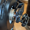
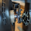
Thank you @Vaklin and @WTFDproject for your responses. I think the magnet looks okay (photos attached). I will check the wires next - thanks for the images. I am certain of the placement of one of the wires because when it was severed, it was still connected by one strand, so that was certainly correct. The other two wires where just a 50/50 guess, so I twist connected them and tested it. Since is seemed to work, I went on to solder. (I had not yet realized there was this limited arc issue.) Hopefully a swap will resolve this. Otherwise, it's a call to service repair.
1663336566549.png 1663336593971.png 1663336611157.png
 
On the side of the ball-type housing are two stoppers. Check them. Someone can do an obstruction. Very often one of them is broken, which doesn't degrade the overall performance of the gimbal, but if this does an obstruction, the things aren't so careless.
 
Correction. You've said upper the gimbal moves freely, so there should be no obstruction.

If the wires swap didn't help, we should go back to the magnet.
 
Also, you can check the pitch by simply tilting the drone and watching will be the camera still horizontal. Do this with the controller switched off.
 
I previously tested the gimbal function using the tilt test. Yaw and roll tracked smoothly. Pitched tracked too, but was limited to the same short arc as with the controller.

New problem - when pulling the wire out of the JST, one wire broke off Ugh! So now I am looking for a spare JST and pigtail to repair that!

Can someone confirm the connector? I think I need a JST-SH 3-Pin 1.00 mm pitch. Sound correct?
 
Update: RESOLVED!

...

New problem - when pulling the wire out of the JST, one wire broke off Ugh! So now I am looking for a spare JST and pigtail to repair that!

Can someone confirm the connector? I think I need a JST-SH 3-Pin 1.00 mm pitch. Sound correct?
Confirmed: This is a JST SH 3-Pin 1.00 mm pitch. (I found some. Used one successfully, have 19 spares to share!)
 
  • Like
Reactions: WTFDproject
Update: RESOLVED!

The problem was that two of the wires leading to the pitch motor where swapped. Reversing the wires resolved the limited arc and enabled full articulation of that motor. (The wires were swapped because they were severed in an accident and reconnected incorrectly.)

@Vaklin and @WTFDproject, thank you very much for your very helpful responses and guidance.
 

New Posts

Members online

No members online now.

Forum statistics

Threads
20,954
Messages
241,586
Members
27,284
Latest member
csandoval