Hello Fellow Yuneec Pilot!
Join our free Yuneec community and remove this annoying banner!
Sign up

how to calibrate IMU?

Joined
Apr 2, 2020
Messages
19
Reaction score
20
Location
Los Angeles
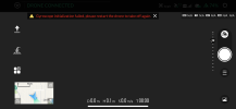
Hello. I have this problem with gyroscope. When I power up the drone everything is fine except this error: Gyroscope initialization failed, please restart the drone to take off again.

23-02-03 19-22-35 3071.png

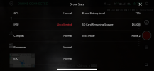
Then right after that it shows the Drone State window where it shows that IMU is Uncalibrated

23-02-03 19-12-44 3070.png

Sure enough restarting the drone does not help. Doing compass calibration does not help. There is no menu option to calibrate anything else than compass and controller.

When I try to launch anyway it does not let me do it and gives another warning message: Motors cannot be armed. Please calibrate the gyrometer before flight

23-02-03 19-23-15 3073.png

Sure I would love to calibrate but how? Anyone has any ideas?

Here are the software version numbers if that helps:

App version: 2.0.4
Drone version: 1.1.07
Remote version: 1.0.02
 
  • Like
Reactions: WTFDproject
I have tried to get the software to solve this issue to no avail whatsoever. Yuneec dropped support for the Mantis series without supplying the software to maintain our own aircraft.

On several that I have encountered it seems to stem from a crash. Whacking a tree, wall, or other obstacle. Sometimes just a hard landing on pavement. Anything that jars the aircraft while powered up.

I have been able to calibrate the IMU while connected to QGroundControl (QGC), but it does not seem to allow the parameters to get stored. As soon as you disconnect from QGC and access via Yuneec Pilot you are left with the same IMU failures.
 
  • Sad
Reactions: Steve Carr
I am going to answer my own question. Got sick last week and had some time at home to look at this issue. Hope it helps people here as it seems to be an unresolved problem.

You can calibrate IMU permanently through UART shell. The downside is that the drone needs to be disassembled and soldering is required to connect to the UART pins. And at the moment of calibration the drone must me in assembled state and all the sensors connected and compass calibrated. Without all sensors respoding the drone will not reach the state where it can execute IMU calibration. So basically you need to disassemble the drone, solder some header with wires to UART so you can route it to outside and then reassemble the drone with the wires sticking out.


Ok step by step:
- connect to UART8 and set speed tp 57600 with the drone assembled and on level surface, compass needs to be already calibrated before this procedure. Power on the drone and while it is booting it pobably will start dropping sensor errors in standard output (in my case it was some Error 11) and messing up the info on the screen, just ignore that and keep going.
- there are buch of commands you can run once it reaches nsh shell prompt. Execute command "sensors status" and you should see that all senors are enabled and connected:

nsh> sensors status
INFO [sensors] gyro status:
INFO [Unknown] validator: best: 0, prev best: 0, failsafe: NO (0 events)
INFO [Unknown] sensor #0, prio: 100, state: OK
INFO [Unknown] val: -0.0042, lp: 0.0000 mean dev: 0.0000 RMS: 0.0041 conf: 1.0000
INFO [Unknown] val: 0.0073, lp: 0.0072 mean dev: -0.0000 RMS: 0.0014 conf: 1.0000
INFO [Unknown] val: -0.0012, lp: -0.0001 mean dev: 0.0000 RMS: 0.0007 conf: 1.0000
INFO [sensors] accel status:
INFO [Unknown] validator: best: 0, prev best: 0, failsafe: NO (0 events)
INFO [Unknown] sensor #0, prio: 100, state: OK
INFO [Unknown] val: 0.0869, lp: 0.0560 mean dev: -0.0003 RMS: 0.0233 conf: 1.0000
INFO [Unknown] val: -0.4212, lp: -0.4296 mean dev: -0.0007 RMS: 0.0251 conf: 1.0000
INFO [Unknown] val: -9.8764, lp: -9.8954 mean dev: 0.0026 RMS: 0.0217 conf: 1.0000
INFO [sensors] mag status:
INFO [Unknown] validator: best: 0, prev best: 0, failsafe: NO (0 events)
INFO [Unknown] sensor #0, prio: 255, state: OK
INFO [Unknown] val: -0.2125, lp: -0.2134 mean dev: 0.0001 RMS: 0.0019 conf: 1.0000
INFO [Unknown] val: -0.0216, lp: -0.0205 mean dev: 0.0001 RMS: 0.0015 conf: 1.0000
INFO [Unknown] val: 0.4751, lp: 0.4718 mean dev: -0.0000 RMS: 0.0028 conf: 1.0000
INFO [sensors] baro status:
INFO [Unknown] validator: best: 0, prev best: 0, failsafe: NO (0 events)
INFO [Unknown] sensor #0, prio: 75, state: OK
INFO [Unknown] val: -14.0850, lp: -14.0920 mean dev: 0.0036 RMS: 0.0220 conf: 1.0000
INFO [Unknown] val: 0.0000, lp: 0.0000 mean dev: 0.0000 RMS: 0.0000 conf: 1.0000
INFO [sensors] Temperature Compensation:
INFO [sensors] gyro: enabled: 1
INFO [sensors] using device ID 3670282 for topic instance 0
INFO [sensors] accel: enabled: 1
INFO [sensors] using device ID 3604746 for topic instance 0
INFO [sensors] baro: enabled: 1
INFO [sensors] using device ID 5600801 for topic instance 0
INFO [sensors] Airspeed status:
INFO [Unknown] no data


- execute "commander status" and you should see output like this which basically means that arming process is stuck in the INIT state:

nsh> commander status
WARN [commander] type: symmetric motion
WARN [commander] safety: USB enabled: [NO], power state valid: [OK]
WARN [commander] avionics rail: 5.05 V
WARN [commander] home: lat = xx.xxxxxx, lon = yy.yyyyyy, alt = 69.77, yaw: -3.04
WARN [commander] home: x = 0.0456430, y = 0.0074987, z = -0.04
WARN [commander] datalink: OK
WARN [commander] main state: 2
WARN [commander] nav state: 2
WARN [commander] arming: INIT


- at this point you can run IMU calibration procedure, execute "commander calibrate gyro". Leave your drone on level surface and watch calibration being performed, it will take a minute or so and the output should show countdown till 100. The output might get messed up with sensor errors but be patient and see thought it:

nsh> commander calibrate gyro
INFO [commander] [cal] calibration started: 2 gyro
INFO [commander] [cal] progress <5>
INFO [commander] [cal] progress <10>
INFO [commander] [cal] progress <15>
....
INFO [commander] [cal] progress <80>
INFO [commander] [cal] progress <85>
INFO [commander] [cal] progress <90>
INFO [commander] [cal] progress <95>
INFO [commander] [cal] progress <100>
INFO [commander] [cal] calibration done: gyro
INFO [commander] Disarmed by init -> standby


- now you can power down the drone and power it up again. Again execute "commander status" and you should see that now the arming was completed and drone is in sate STANDBY, ready to launch.

nsh> commander status
WARN [commander] type: symmetric motion
WARN [commander] safety: USB enabled: [NO], power state valid: [OK]
WARN [commander] avionics rail: 5.04 V
WARN [commander] home: lat = xx.xxxxxx, lon = yy.yyyyyy, alt = 70.16, yaw: -3.06
WARN [commander] home: x = 0.0593491, y = 0.0035389, z = -0.11
WARN [commander] datalink: OK
WARN [commander] main state: 2
WARN [commander] nav state: 2
WARN [commander] arming: STANDBY


The IMU should be calibrated and you can fly your Mantis-Q.
 
Last edited:
So basically you need to disassemble the drone, solder some header with wires to UART so you can route it to outside and then reassemble the drone with the wires sticking out.


Ok step by step:
- connect to UART8 and set speed tp 5


nsh> commander status
WARN [commander] type: symmetric motion
WARN [commander] safety: USB enabled: [NO], power state valid: [OK]
WARN [commander] avionics rail: 5.04 V
WARN [commander] home: lat = xx.xxxxxx, lon = yy.yyyyyy, alt = 70.16, yaw: -3.06
WARN [commander] home: x = 0.0593491, y = 0.0035389, z = -0.11
WARN [commander] datalink: OK
WARN [commander] main state: 2
WARN [commander] nav state: 2
WARN [commander] arming: STANDBY


The IMU should be calibrated and you can fly your Mantis-Q.
This could be a very important process if enough folks can use it. But I believe most of us will need more detail. A couple I see are:
.Solder some wires with header to .....
A snapshot of the connections and a diagram of where to connect would help a lot here.

"...the wires sticking out.
...........................

- connect to UART8"
What goes between these two points? What are the wires connected to? How is it connected to the computer?

If you could do video or screen shots of the needed computer actions, it would be great.
 
I am going to answer my own question. Got sick last week and had some time at home to look at this issue. Hope it helps people here as it seems to be an unresolved problem.

You can calibrate IMU permanently through UART shell. The downside is that the drone needs to be disassembled and soldering is required to connect to the UART pins. And at the moment of calibration the drone must me in assembled state and all the sensors connected and compass calibrated. Without all sensors respoding the drone will not reach the state where it can execute IMU calibration. So basically you need to disassemble the drone, solder some header with wires to UART so you can route it to outside and then reassemble the drone with the wires sticking out.


Ok step by step:
- connect to UART8 and set speed tp 57600 with the drone assembled and on level surface, compass needs to be already calibrated before this procedure. Power on the drone and while it is booting it pobably will start dropping sensor errors in standard output (in my case it was some Error 11) and messing up the info on the screen, just ignore that and keep going.
- there are buch of commands you can run once it reaches nsh shell prompt. Execute command "sensors status" and you should see that all senors are enabled and connected:

nsh> sensors status
INFO [sensors] gyro status:
INFO [Unknown] validator: best: 0, prev best: 0, failsafe: NO (0 events)
INFO [Unknown] sensor #0, prio: 100, state: OK
INFO [Unknown] val: -0.0042, lp: 0.0000 mean dev: 0.0000 RMS: 0.0041 conf: 1.0000
INFO [Unknown] val: 0.0073, lp: 0.0072 mean dev: -0.0000 RMS: 0.0014 conf: 1.0000
INFO [Unknown] val: -0.0012, lp: -0.0001 mean dev: 0.0000 RMS: 0.0007 conf: 1.0000
INFO [sensors] accel status:
INFO [Unknown] validator: best: 0, prev best: 0, failsafe: NO (0 events)
INFO [Unknown] sensor #0, prio: 100, state: OK
INFO [Unknown] val: 0.0869, lp: 0.0560 mean dev: -0.0003 RMS: 0.0233 conf: 1.0000
INFO [Unknown] val: -0.4212, lp: -0.4296 mean dev: -0.0007 RMS: 0.0251 conf: 1.0000
INFO [Unknown] val: -9.8764, lp: -9.8954 mean dev: 0.0026 RMS: 0.0217 conf: 1.0000
INFO [sensors] mag status:
INFO [Unknown] validator: best: 0, prev best: 0, failsafe: NO (0 events)
INFO [Unknown] sensor #0, prio: 255, state: OK
INFO [Unknown] val: -0.2125, lp: -0.2134 mean dev: 0.0001 RMS: 0.0019 conf: 1.0000
INFO [Unknown] val: -0.0216, lp: -0.0205 mean dev: 0.0001 RMS: 0.0015 conf: 1.0000
INFO [Unknown] val: 0.4751, lp: 0.4718 mean dev: -0.0000 RMS: 0.0028 conf: 1.0000
INFO [sensors] baro status:
INFO [Unknown] validator: best: 0, prev best: 0, failsafe: NO (0 events)
INFO [Unknown] sensor #0, prio: 75, state: OK
INFO [Unknown] val: -14.0850, lp: -14.0920 mean dev: 0.0036 RMS: 0.0220 conf: 1.0000
INFO [Unknown] val: 0.0000, lp: 0.0000 mean dev: 0.0000 RMS: 0.0000 conf: 1.0000
INFO [sensors] Temperature Compensation:
INFO [sensors] gyro: enabled: 1
INFO [sensors] using device ID 3670282 for topic instance 0
INFO [sensors] accel: enabled: 1
INFO [sensors] using device ID 3604746 for topic instance 0
INFO [sensors] baro: enabled: 1
INFO [sensors] using device ID 5600801 for topic instance 0
INFO [sensors] Airspeed status:
INFO [Unknown] no data


- execute "commander status" and you should see output like this which basically means that arming process is stuck in the INIT state:

nsh> commander status
WARN [commander] type: symmetric motion
WARN [commander] safety: USB enabled: [NO], power state valid: [OK]
WARN [commander] avionics rail: 5.05 V
WARN [commander] home: lat = xx.xxxxxx, lon = yy.yyyyyy, alt = 69.77, yaw: -3.04
WARN [commander] home: x = 0.0456430, y = 0.0074987, z = -0.04
WARN [commander] datalink: OK
WARN [commander] main state: 2
WARN [commander] nav state: 2
WARN [commander] arming: INIT


- at this point you can run IMU calibration procedure, execute "commander calibrate gyro". Leave your drone on level surface and watch calibration being performed, it will take a minute or so and the output should show countdown till 100. The output might get messed up with sensor errors but be patient and see thought it:

nsh> commander calibrate gyro
INFO [commander] [cal] calibration started: 2 gyro
INFO [commander] [cal] progress <5>
INFO [commander] [cal] progress <10>
INFO [commander] [cal] progress <15>
....
INFO [commander] [cal] progress <80>
INFO [commander] [cal] progress <85>
INFO [commander] [cal] progress <90>
INFO [commander] [cal] progress <95>
INFO [commander] [cal] progress <100>
INFO [commander] [cal] calibration done: gyro
INFO [commander] Disarmed by init -> standby


- now you can power down the drone and power it up again. Again execute "commander status" and you should see that now the arming was completed and drone is in sate STANDBY, ready to launch.

nsh> commander status
WARN [commander] type: symmetric motion
WARN [commander] safety: USB enabled: [NO], power state valid: [OK]
WARN [commander] avionics rail: 5.04 V
WARN [commander] home: lat = xx.xxxxxx, lon = yy.yyyyyy, alt = 70.16, yaw: -3.06
WARN [commander] home: x = 0.0593491, y = 0.0035389, z = -0.11
WARN [commander] datalink: OK
WARN [commander] main state: 2
WARN [commander] nav state: 2
WARN [commander] arming: STANDBY


The IMU should be calibrated and you can fly your Mantis-Q.
I am very interested in this. As stated in the post by @WTFDproject a more detailed explanation would help.

Another issue is that the compass cannot be calibrated if the IMU fails. The compass calibration relies on the IMU to know what position the aircraft is in to go through the compass calibration.

To connect to UART 8 you need to connect to pads marked TX8 and RX8 on the PCB. Sorry did not take pictures of every step because at that point I was just blindly exploring the board trying to understand what can be found.

The compass can be calibrated independently from IMU. That is what I said in my first message in this thread - I can calibrate the compass straight from the app but there is no way to calibrate the IMU.
Also, if the compass calibration fails from GUI then there is a great chance that compass does not work. This broken Mantis-Q drone that I got from a friend came with a bad compass, I was not able to calibrate it because the procedure failed instantly. So I purchased a compass online for like $6 + shipping and that one passed calibration w/o issues. So the last issue that remained was that IMU that needs calibration.
Also, I am confident that compass can be calibrated with the commander command just like the gyro is. Just need to run "commander calibrate compass". Did not try that since I was able to calibrate mine from app.
 
This could be a very important process if enough folks can use it. But I believe most of us will need more detail. A couple I see are:
.Solder some wires with header to .....
A snapshot of the connections and a diagram of where to connect would help a lot here.

"...the wires sticking out.
...........................

- connect to UART8"
What goes between these two points? What are the wires connected to? How is it connected to the computer?

If you could do video or screen shots of the needed computer actions, it would be great.
Well yes I guess it needs more detail. But I was not trying to write a complete tutorial, I assumed people doing drone repairs have understanding about such things. I can assure you that this procedure should not be performed by an absolute beginner because just taking this drone apart is quite challenging without screwing up something. The motherboard is quite hard to pull out even when there is nothing holding it down. And you need to be very good with soldering iron, there is no room for mistakes.

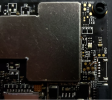
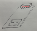
So to connect UART to your computer you need 3 wires, two signal wires and a ground. Find solder points on the motherboard that are marked TX8 and RX8, as you can see they are marked very clearly (I reused the pic from another thread here just added my highlight).
1678151480930.png

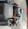
Connect two wires to these points and third wire to any ground point, there are a few marked as GND. As for the "some wires with header" I used what I guess was an old audio header cable from an old PC motherboard that I cut to the length so I can access these pins when drone is reassembled (in the pic you see more wires because I tried other connections as well but you dont need that).
1678151664647.png


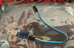
Then you need any USB to UART adapter that can handle 3.3v signaling, in my case I am using Silicon Labs CP2014 based adapter.

1678151743202.png

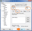
Connect TX8 from the header to RX pin on the UART adapter, RX8 to TX pin on the UART adapter and GND to GND on the UART adapter. Now plug the USB to UART adapter in your PC and go to Device manager and find what COM port number has been assigned to your USB to UART adapter. Then use any terminal client (I used "putty") to connect to that COM port (in my case COM9), set baud rate to 57600 and connect. Now put your drone on level surface, turn it on and follow the procedure I described earlier.

1678151761802.png
 
,,,,. Now put your drone on level surface, turn it on and follow the procedure I described earlier.
In the earlier post with the procedure, you mentioned "... there are buch of commands you can run once it reaches nsh shell prompt".
Does it reach the nsh shell prompt by itself or do you have to start a supporting program? I ask because the current wording seems to imply (at least to me) that if "Putty" is already configured on the PC, the nsh shell prompt will come up.
 
  • Like
Reactions: Steve Carr
Probably the communication is based between the copter and any remote terminal. Not so big deal to try.

Ignore the "nut shell prompt" in the message and go ahead. PuTTY is a good candidate too. I have not exactly this bird to try. Sorry.
 
Well yes I guess it needs more detail. But I was not trying to write a complete tutorial, I assumed people doing drone repairs have understanding about such things. I can assure you that this procedure should not be performed by an absolute beginner because just taking this drone apart is quite challenging without screwing up something. The motherboard is quite hard to pull out even when there is nothing holding it down. And you need to be very good with soldering iron, there is no room for mistakes.

So to connect UART to your computer you need 3 wires, two signal wires and a ground. Find solder points on the motherboard that are marked TX8 and RX8, as you can see they are marked very clearly (I reused the pic from another thread here just added my highlight).
View attachment 29080

Connect two wires to these points and third wire to any ground point, there are a few marked as GND. As for the "some wires with header" I used what I guess was an old audio header cable from an old PC motherboard that I cut to the length so I can access these pins when drone is reassembled (in the pic you see more wires because I tried other connections as well but you dont need that).
View attachment 29081


Then you need any USB to UART adapter that can handle 3.3v signaling, in my case I am using Silicon Labs CP2014 based adapter.

View attachment 29082

Connect TX8 from the header to RX pin on the UART adapter, RX8 to TX pin on the UART adapter and GND to GND on the UART adapter. Now plug the USB to UART adapter in your PC and go to Device manager and find what COM port number has been assigned to your USB to UART adapter. Then use any terminal client (I used "putty") to connect to that COM port (in my case COM9), set baud rate to 57600 and connect. Now put your drone on level surface, turn it on and follow the procedure I described earlier.

View attachment 29083
@flashcoder just wanted to send thanks for sharing this with the group. While it has not allowed me to remedy the issue with the one I have on hand, it has allowed me access to experiment more with repairing it.
 
@flashcoder just wanted to send thanks for sharing this with the group. While it has not allowed me to remedy the issue with the one I have on hand, it has allowed me access to experiment more with repairing it.

Youre welcome. Yes there are lot of commands to explore, I have not done more research myself yet. What is the issue that you have with IMU? Have you carefully looked through all the errors that get logged in the console as the drone is powering up? There could be lots of useful info. Also if you have a backup of the 8Gb internal SD card (not the camera SD card) you should try to restore it and see if that helps, there is file called params that holds values that drone needs to power up properly.
In my case I had many things wrong with my drone which I got already broken, bad compass, bad GPS, cracked that internal SD card (this one I could have caused myself) and I was able to get things fixed one by one. One thing I suggest you to look at are the pins inside all these slim connectors - GPS, compass, ultrasonic sensor, the male side pins can bend easily if the connector gets inserted a bit crooked and will cause shorts in the pins resulting in sensors not detected or shorted power supply etc and that in turn does now allow the drone to continue boot properly and it either fails with some error or keeps looping.

You mentioned you were able to calibrate IMU using QGroundControl but it does not save the calibration. Suggest you to try a different internal SD card, maybe the card is damaged internally and cant save the calibration settings. I think that calibration is saved in params file but I could be wrong.
 
Already checked all of the connectors on this one. It was sent to me after a crash and was failing gyros and accelerometers. I tried using QGC on this one as I had others in the past and I can only connect via WiFi instead of through the USB port (USB works to transfer SD card for camera). When I attempted a compass cal it got hung at the first step and never gave the beep to start turning, and I now get a compass needs to be calibrated after power up initialization.

The comms from UART8 go through init and then loop with error 10. The only way to break that loop and get the nsh> prompt is to connect with the app or QGC via WiFi and start a calibration routine. Those always hang at the first step and never progress.

I will check the internal SD card when I get a chance to start experimenting again.

Your insights are very appreciated.
 
  • Like
Reactions: Steve Carr
If it cant go through compass calibration I would suspect a dead compass, I know mine was dead because I finally noticed that the little 3.3v regulator that powers the compass BGA chip on the little compass PCB was heating up like crazy once drone was powered on, noticed that by accidental touch of a finger. But in my case the calibration failed instantly as soon as I attempted to perform it, a red error popped up in the app saying that calibration failed. In your case the chip might have a different type of damage where the chip does not respond over I2C. Maybe a chip damage could happen if connectors got mixed up and compass got plugged in optical/ultrasound sensor connector by mistake, its easy to mix them since the connectors are the same. If I recall correctly the the pinout of Optical flow sensor is not the same as for compass therefore I believe a damage could occur. But again I am not sure, I do not remember it for sure. I found in my notes only the pinout of the little compass module, you may want to check at least that +5 voltage are present at the connector and at the 3.3v regulator and if you have an oscilloscope you could check if any activity over the I2C is happening.

1678514601264.png
 
Thanks for the info. I’ll have to wait until I return to Michigan to have access to my oscope. The connectors were not mixed when this occurred as the aircraft had not been opened yet. You do have a point as the aircraft had been flown backwards into a tree so there may be an issue in that regard. I know I2C is sensitive to resistive connections so I’ll do some more probing.

Guess I could get a logic analyzer that works via USB with my laptop. A lot more portable than a real oscope.
 
  • Like
Reactions: Steve Carr
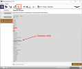
You can also check if compass is accessible by nsh shell via QGC:
cd dev
ls
will list all active periphery. Picture is from Typhoon H, not Mantis because I do not have one.
HW_list.png
Compass should be something like ist8310_ext. I do not know what chip is used in Mantis drone. Someone knows?

If compass calibration does something you can check if parameters
CAL_MAG0_XOFF
CAL_MAG0_XSCALE
CAL_MAG0_YOFF
CAL_MAG0_YSCALE
CAL_MAG0_ZOFF
CAL_MAG0_ZSCALE
changed before and after calibration. Changing do not mean that calibration was succesful but if during calibation was something written to parameters.

I do not believe that parameters are stored on SD card becuse PX4 autopilot works also without SD card. I guess this is a backup or more probable the default (factory) settings.

For couriosity I would like to see such a parameter file from Mantis drone and a screenshot from HW list.

br HE
 
  • Like
Reactions: Steve Carr
You can also check if compass is accessible by nsh shell via QGC:
cd dev
ls
will list all active periphery. Picture is from Typhoon H, not Mantis because I do not have one.
View attachment 29109
Compass should be something like ist8310_ext. I do not know what chip is used in Mantis drone. Someone knows?

If compass calibration does something you can check if parameters
CAL_MAG0_XOFF
CAL_MAG0_XSCALE
CAL_MAG0_YOFF
CAL_MAG0_YSCALE
CAL_MAG0_ZOFF
CAL_MAG0_ZSCALE
changed before and after calibration. Changing do not mean that calibration was succesful but if during calibation was something written to parameters.

I do not believe that parameters are stored on SD card becuse PX4 autopilot works also without SD card. I guess this is a backup or more probable the default (factory) settings.

For couriosity I would like to see such a parameter file from Mantis drone and a screenshot from HW list.

br HE
I’m busy tomorrow, but will try to get that on Monday.

When you connect QGC to the H do you use the USB port to access the nsh shell?

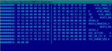
I’ll also try to get a hex dump of the param file that is on the internal SD card.

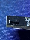
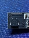
Here is a photo of the compass chip.
C7ACFFE1-5FD1-43C7-8ACD-3C7CAE729EBF.jpeg
3B01AF74-F78C-4EAF-9D97-85617BF8E73D.jpeg
 
  • Like
Reactions: Steve Carr
Thanks, Mantis' compass chip is ISENTEK IST8310. Good to know. It should appear as such in HW list
nsh> /dev/

br HE
It does show there. I’ll send some logs from UART sessions later. Can only connect to QGC via WiFi and unable to use QGC’s nsh> over WiFi. QGC fails to make a connection over the UART8.
 

New Posts

Members online

Forum statistics

Threads
21,188
Messages
244,317
Members
27,965
Latest member
Mhinkle1983