Hello Fellow Yuneec Pilot!
Join our free Yuneec community and remove this annoying banner!
Sign up

how to calibrate IMU?

I like the idea of trying to run a public version of PX4 on both versions of the Mantis. I agree we should do it under the thread you posted.

BTW the signals are also on the Debug port at the edge of the board.
GND is the last pin right above the U in debug (pin 6).
TX8 is pin 2.
RX8 is pin 3

If this is a typical PX4 debug port then the other pins are defined online. I’ll try to revisit that soon as I stumbled across it a couple days ago. A proper connector could be added to the pads, but getting to it would still be an issue. The pigtail works well for now.

I'm also attempting to trace the signals on the connector of the GPS board. I need to find a place to mount my lighted magnifying stand here in Florida and hope it is enough to see some of the pins for the IMU chip. My needle probes are having trouble hitting the right spot without a magnifier.
 
Last edited:
  • Like
Reactions: Pier2162
Guys, you'll force me to buy a G ;)

Good job, good efforts. Well done!

What interesting will be to implement the SR24 transceiver with the idea to use ST10 with it?
 
  • Like
Reactions: Steve Carr
Yeah, buy one, lets get the scene moving :)
You can snatch them up pretty cheap on eBay if youre lucky. Like this eBay deal (open the ended item, not the one eBay promotes as alternative), someone got a very good deal, full drone package at a price of a battery (the battery was probably dead as they always are), I was looking at it, very tempted to buy it but I thought I already have too many drones and no time so I did not buy it. But keep looking things pop up there now and then.
 
Are the Q and the G on the same platform?
AFAIK, Q is with a fixed camera, which is not good for a "fast look on the scene".
 
Not 100% sure. The remote is the same, the app is the same, probably the PX4 side is the same on both of them. Mantis Q has 1 axis the gimbal, just up and down camera like on Breeze, it probably has some digital stabilization, I have not paid attention to it, its not a serious videographers drone. But look at the positive side - that is why it is cheap in used market, no one wants it, great platform for DIY and projects. Mantis G has 2-axis gimbal but its not just that what is different, the main board is certainly different so its not like you can swap gimbal from Mantis G to Mantis Q. But I think Yuneec originally had plans to add gimbal on Mantis Q because its visible on the main board that they had that in mind but then for whatever reason dropped it. Or planned to have another model based on Mantis Q. So there you go, maybe its possible to implement a small 3rd party gimbal, maybe they already have a code in place there. Anyways, as far as I could see the code on PX4 side has evidence that it has been prepared for several different drones not just Mantis Q and G. Just need to start digging.
 
The Q and the G use different controllers although the G controller will work with the Q.

While they are close functionally, the internal electronics are different and are not interchangeable.

The SR24 is not used in the Mantis series so the ST controllers will not work. They use WiFi for control and video.

The Android version of the app seems to have issues with Android OS greater than 8. The video feed does not show on the phone. Yuneec dropped support so this issue was never fixed.
 
  • Like
Reactions: Vaklin
I lost interest. Thank you!
The H 480 is well-explored for me, so I'll stay on it.
 
I use an Umidigi F1 Play for the Mantis Q. As a pure flying phone without a SIM card
 
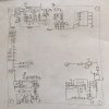
I traced out as much of the GPS board as I can with just a multimeter. I will try to clean it up later on. A3E1BAA1-F62B-4180-8300-0F0C923364AC.jpeg
The outer pins of the connector that go to the Main board carry Ground and what I refer to as Vcc I suspect it to be either 3.3V or 5V from the Main board.

CS, SPC, SDO, and SDI are the SPI interface to the IMC-20602 IMU chip. The INT signal on pin 6 of the 20602 seems to have no discernible connection.

I believe the pins next to Vcc in the connector are the I2C comms that are connected to the Barometer IC (no exposed pins) and the U-Blox EVA-M8Q GPS IC (no exposed pins).

Signals 5, 6, and 7 interface to the memory IC near the Baro.

The signal labeled ? seems to be derived from Vcc through a voltage divider encompassing the 4 510 resistors and the small MOSFET.

Hoping to scope these when I return to Michigan.
 

New Posts

Members online

No members online now.

Forum statistics

Threads
21,180
Messages
244,265
Members
27,948
Latest member
liimamake85