I'm interested in this too...When you connect QGC to the H do you use the USB port to access the nsh shell?
You are using an out of date browser. It may not display this or other websites correctly.
You should upgrade or use an alternative browser.
You should upgrade or use an alternative browser.
how to calibrate IMU?
- Thread starter flashcoder
- Start date
h-elsner
Premium Pilot
- Joined
- Mar 23, 2016
- Messages
- 2,400
- Reaction score
- 2,162
- Location
- Bavaria / Germany
- Website
- h-elsner.mooo.com
Sorry, misleading. The HW list is from Typhoon H but one with PX4 Firmware (Thunderbird FW from Pöllö).When you connect QGC to the H do you use the USB port to access the nsh shell?
Discussion here: Typhoon H 480 PX4 v1.10 (Stability issues ;-)
Access only via USB Port but I try to get a serial connection working to use a MAVlink bridge via WiFi - the same thing that can imitate a camera for H520.
Discussion here: Streaming telemetry without a camera
br HE
I thought I posted this last night, but I must have made the post and failed to send it.
Attached is the "params" file from the internal SD card on the Mantis. Remove the ".txt" as it is only so it will upload to the forum, there is no file extension.
The other attachment is some excerpts from UART8 as described earlier by @flashcoder. Hopefully @h-elsner can gain some info from them.
Attached is the "params" file from the internal SD card on the Mantis. Remove the ".txt" as it is only so it will upload to the forum, there is no file extension.
The other attachment is some excerpts from UART8 as described earlier by @flashcoder. Hopefully @h-elsner can gain some info from them.
Attachments
I thought I posted this last night, but I must have made the post and failed to send it.
Attached is the "params" file from the internal SD card on the Mantis. Remove the ".txt" as it is only so it will upload to the forum, there is no file extension.
The other attachment is some excerpts from UART8 as described earlier by @flashcoder. Hopefully @h-elsner can gain some info from them.
Wow, your params file contains alot more parameters! The screenshot of mine I posted earlier its the entire params file in my case! I am getting alot of "error finding param:" messages when my drone is initializing, I just did not paste all that bloated log here so not to confuse ppl here. But I just went though your log file comparing "error finding param:" messages to my log file and I have exactly the same messages with the same parameter errors. Weird.
Now I think I found your problem, you have this IMU error in your log file:
Code:
WARN [mpu6000] no device on bus 3My logfile has this message instead:
Code:
MPU6000 on SPI bus 1 at 1 (1000 KHz)
INFO  [mpu6000] accel cutoff set to 30.00 Hz
INFO  [mpu6000] gyro cutoff set to 65.00 Hz
Which means it literally cant find your Inertia Management Unit (IMU) chip MPU6000. Maybe it is looking for it on the wrong bus? Because mine is on SPI bus 1. Maybe that is controlled by a parameter somewhere which somehow points to a wrong bus?
Maybe you should copy paste my small params file into your SD card and see if forces the PX4 to use some built-in default values during the startup and force it find that MPU6000 on a SPI bus 1?
I have my params file attached. Also a link to file compare of both log files one from your drone and one from mine.
Link to diff:
Attachments
I loaded your param file on a freshly formatted SD card and installed it in my Mantis Q. It still failed with the same readings from UART 8. I am attaching the file that resulted after booting in my aircraft.
I am definitely missing the mpu6000 IMU as it fails to show in active devices. I'm assuming it is mounted somewhere on the Main Board, but not sure of that.
I am definitely missing the mpu6000 IMU as it fails to show in active devices. I'm assuming it is mounted somewhere on the Main Board, but not sure of that.
Attachments
These drawings are to supplement yours.If it cant go through compass calibration I would suspect a dead compass, I know mine was dead because I finally noticed that the little 3.3v regulator that powers the compass BGA chip on the little compass PCB was heating up like crazy once drone was powered on, noticed that by accidental touch of a finger. But in my case the calibration failed instantly as soon as I attempted to perform it, a red error popped up in the app saying that calibration failed. In your case the chip might have a different type of damage where the chip does not respond over I2C. Maybe a chip damage could happen if connectors got mixed up and compass got plugged in optical/ultrasound sensor connector by mistake, its easy to mix them since the connectors are the same. If I recall correctly the the pinout of Optical flow sensor is not the same as for compass therefore I believe a damage could occur. But again I am not sure, I do not remember it for sure. I found in my notes only the pinout of the little compass module, you may want to check at least that +5 voltage are present at the connector and at the 3.3v regulator and if you have an oscilloscope you could check if any activity over the I2C is happening.
View attachment 29106
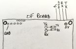
Optical Flow board
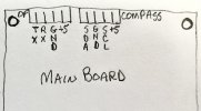
Connector pinout for OF and Compass on Main board. Not sure if swapping would damage the Optical Flow board, but may affect the Compass.
h-elsner
Premium Pilot
- Joined
- Mar 23, 2016
- Messages
- 2,400
- Reaction score
- 2,162
- Location
- Bavaria / Germany
- Website
- h-elsner.mooo.com
To see what's in those txt/bin mixed parameter files I have a quick&dirty programm to convert it to readable format. If someone is intersted in...
br HE
Edit: Drag&Drop added
br HE
Edit: Drag&Drop added
Attachments
Last edited:
As always you are the programmer on the spot! Nice work and developed quickly. Are a lot of these parameters defined in the PX4 docs? It would have been nice if Yuneec just used PX4 instead of their own "flavor" of it.To see what's in those txt/bin mixed parameter files I have a quick&dirty programm to convert it to readable format. If someone is intersted in...
br HE
h-elsner
Premium Pilot
- Joined
- Mar 23, 2016
- Messages
- 2,400
- Reaction score
- 2,162
- Location
- Bavaria / Germany
- Website
- h-elsner.mooo.com
I have not checked all, but I couldn't find one that is not described here:
 dev.px4.io
The only one that looks strange is "TE_D" but this part looks destroyed/broken somehow. I think it should mean "MC_ROLLRATE_D". which would make sense at this place.
br HE
Parameter Reference · PX4 Developer Guide
The only one that looks strange is "TE_D" but this part looks destroyed/broken somehow. I think it should mean "MC_ROLLRATE_D". which would make sense at this place.
br HE
I have searched every board in the Mantis Q and cannot find the mpu6000 IMU IC unless what Yuneec used is in a different formfactor and not labeled with anything that comes up in a web search. I will list the IC's I have identified and add photos showing location. I will also add photos of the chips i cannot ID in hopes that others may find the answer.
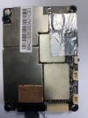
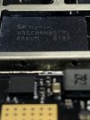
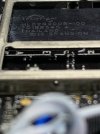
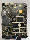
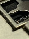
Main Top LPDDR3 Mem NAND Flsh Mem Memory Loc ARM STM32F765
On the top side of the main board under the metal cover with the silver foil is the STM32F765
Under the metal cover just below that is a chip I can't ID on the web. It is a square SMD IC with 8 leads on each side the ID markings are: first line ES 5A, second line QOH. Can't photo due to position of cover.
Under the metal cover with the copper foil is an Ambarella chip for the camera.
Under the metal cover with the MAC Addr are an RTL8812AU dual channel WiFi IC and a SKY85728-11 5 GHz WiFi FEM (Front End Module)
The memory modules are under a large metal cover on the bottom side of the Main board.
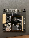
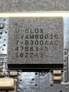
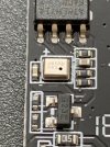
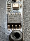
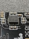
GPS board U-Blox GPS Barometer ATMLH714 16 pin IC ?
Above is the GPS board and the IC's on it. I cannot find a datasheet for the ATMLH714 or any information on the 16 pin IC leads 5x3x5x3.
The Optical Flow board has an ATMEL ATSAME70N19 processor and a 3PEAK TP2414 OpAmp.
The Compass board has an IST8310 compass IC.


Main Top LPDDR3 Mem NAND Flsh Mem Memory Loc ARM STM32F765
On the top side of the main board under the metal cover with the silver foil is the STM32F765
Under the metal cover just below that is a chip I can't ID on the web. It is a square SMD IC with 8 leads on each side the ID markings are: first line ES 5A, second line QOH. Can't photo due to position of cover.
Under the metal cover with the copper foil is an Ambarella chip for the camera.
Under the metal cover with the MAC Addr are an RTL8812AU dual channel WiFi IC and a SKY85728-11 5 GHz WiFi FEM (Front End Module)
The memory modules are under a large metal cover on the bottom side of the Main board.


GPS board U-Blox GPS Barometer ATMLH714 16 pin IC ?
Above is the GPS board and the IC's on it. I cannot find a datasheet for the ATMLH714 or any information on the 16 pin IC leads 5x3x5x3.
The Optical Flow board has an ATMEL ATSAME70N19 processor and a 3PEAK TP2414 OpAmp.
The Compass board has an IST8310 compass IC.
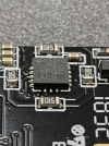
The IMU chip is on the GPS board, this LGA16 chip you made picture of is ICM-20602, that is the IMU:
Datasheet at TDK: icm-20602
I recall reading in drone forums that by design IMU is often required to be dampened from vibrations of the frame and preferably away from electromagnetic interference, so it makes sense that they moved it to GPS board because there it is somewhat shielded and better dampened than main PCB.
So why there is no MPU6000 chip but PX4 still finds it? Based on what I found in internets I will try to explain. The MPU6000 chip is not there because it was no longer produced as InvenSense (now TDK as InvenSense was bought by TDK) announced EOL for this chip since early 2019. Obviously TDK being TDK designed newer IMU chips to replace MPU6000, originally ICM-20689 was designed as a replacement albeit not exactly pin compatible. But TDK also produces bunch of other IMU chips in different packages as well and some of them still have that backwards compatibility at least at the registers level and such. So my guess is that Yuneec had a driver originally for MPU6000 and when it became clear that it will be obsolete they just dropped in a compatible replacement and since the driver worked fine they did not care to change anything and so it still says MPU6000 in the logs.
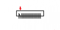
But before you rip that chip off the board double check your connections. You probably have checked but I will say it again that the male side connectors can have bent pins and you would not notice that immediately. So look inside the male connectors because I had exactly this issue when I got my broken Mantis-Q, someone before me was trying to fix it had bent the pins like this:
But if you trace every wire of that cable connection and its all good and voltages also are there then here is the link to that chip on aliexpress:
ICM-20602 LGA-16 on aliexpress

Datasheet at TDK: icm-20602
I recall reading in drone forums that by design IMU is often required to be dampened from vibrations of the frame and preferably away from electromagnetic interference, so it makes sense that they moved it to GPS board because there it is somewhat shielded and better dampened than main PCB.
So why there is no MPU6000 chip but PX4 still finds it? Based on what I found in internets I will try to explain. The MPU6000 chip is not there because it was no longer produced as InvenSense (now TDK as InvenSense was bought by TDK) announced EOL for this chip since early 2019. Obviously TDK being TDK designed newer IMU chips to replace MPU6000, originally ICM-20689 was designed as a replacement albeit not exactly pin compatible. But TDK also produces bunch of other IMU chips in different packages as well and some of them still have that backwards compatibility at least at the registers level and such. So my guess is that Yuneec had a driver originally for MPU6000 and when it became clear that it will be obsolete they just dropped in a compatible replacement and since the driver worked fine they did not care to change anything and so it still says MPU6000 in the logs.
But before you rip that chip off the board double check your connections. You probably have checked but I will say it again that the male side connectors can have bent pins and you would not notice that immediately. So look inside the male connectors because I had exactly this issue when I got my broken Mantis-Q, someone before me was trying to fix it had bent the pins like this:

But if you trace every wire of that cable connection and its all good and voltages also are there then here is the link to that chip on aliexpress:
ICM-20602 LGA-16 on aliexpress
Last edited:
Memory Atmel AT93C46ATMLH714 16 pin IC ?
The square chip is the IMU.
Thank you @flashcoder and @Vaklin
I have thoroughly checked the socket pins on the GPS board and the Main board and checked continuity with the cable plugged in from the board side between both.
I have seen this condition on both Mantis Q and G models that have been in a crash or roughly handled during shipping. Seems very odd. I will check voltages soon (have to do my taxes today - #&*#*!!).
Given that IMU is basically an electro-mechanical device (MEMS) then its probably possible that it can get damaged if whacked. Not sure if just crashing a drone is enough, maybe falling on the concrete is but then drone itself would be broken as well.. And then it also has quite limited lifespan in terms of guaranteed MTBF hours.
- Joined
- Dec 3, 2016
- Messages
- 8
- Reaction score
- 1
- Age
- 73
I haven't read all the responses, and forgive me if this is too basic, but here are my thoughts. When you turn the quad on, it must remain still for long enough for all sensors to initialize (maybe a minute or so). So it you switch it on while holding it upside down, then turn it over to sit it on the ground or table, it's not going to be happy. Hope this helps.Hello. I have this problem with gyroscope. When I power up the drone everything is fine except this error: Gyroscope initialization failed, please restart the drone to take off again.
View attachment 28967
Then right after that it shows the Drone State window where it shows that IMU is Uncalibrated
View attachment 28965
Sure enough restarting the drone does not help. Doing compass calibration does not help. There is no menu option to calibrate anything else than compass and controller.
When I try to launch anyway it does not let me do it and gives another warning message: Motors cannot be armed. Please calibrate the gyrometer before flight
View attachment 28966
Sure I would love to calibrate but how? Anyone has any ideas?
Here are the software version numbers if that helps:
App version: 2.0.4
Drone version: 1.1.07
Remote version: 1.0.02
This is true, but the aircraft initializes in under 5 seconds. I always power up my drones with them sitting on a solid surface. Acquisition of good GPS will take anywhere from 1 to 13 minutes depending on how long the aircraft has been inactive.I haven't read all the responses, and forgive me if this is too basic, but here are my thoughts. When you turn the quad on, it must remain still for long enough for all sensors to initialize (maybe a minute or so). So it you switch it on while holding it upside down, then turn it over to sit it on the ground or table, it's not going to be happy. Hope this helps.
The issues in this thread are results from aircraft that have sustained crash damage. Since Yuneec no longer services these aircraft we are all attempting to find solutions on our own.
It would really help if Yuneec would release the tech docs for its legacy drones along with the software that was used in troubleshooting. The technology is old enough now that I don’t see it as a threat to their business.
They are focused on the high end big bucks market now anyway. There are very few prosumer drone enthusiasts that are willing to spend upwards of $20,000 to get started with the latest Yuneec technology, and that doesn’t even include the software cost to process the imagery captured.
They are focused on the high end big bucks market now anyway. There are very few prosumer drone enthusiasts that are willing to spend upwards of $20,000 to get started with the latest Yuneec technology, and that doesn’t even include the software cost to process the imagery captured.
All drone market is oriented toward the military now. So, no old or new technology, everything is usable. USD 200 FPV drone very well utilizes a few tenths of millions of war equipment with only one mission.
If someone asks to buy the documents, they probably will get a negotiation but just to release them to the public for free is nonsense.
If someone asks to buy the documents, they probably will get a negotiation but just to release them to the public for free is nonsense.
Yes it is not likely that Yuneec is going to release anything to the public. Because even military drones are based on the same (good old) technologies that were/still are used in consumer drones, that would make their current products vulnerable for whatever possible exploits, that is just one argument. Even if they wanted to help enthusiasts they will not, sure its about money, too- they would much rather build and sell you a drone that people want if there is a sufficient market instead of allowing people to build one "for free" using their tools/software/intellectual property (its never exactly free but for sake of simplicity)..
So I guess the only way to keep using these old drones is to dig in figure out everything ourselves. Technically they cant say anything about that because they dropped support. The drone you own is your drone you paid money for it, its yours. They are not obliged to release any intellectual property but neither they can stop you from doing whatever you want to do with it. Maybe I am wrong but as an absolute minimum it falls under the "right to repair". My position is that if I own some device I can do what I want with it within the boundaries of law. So you own a device - you can modify device yourself as you see fit, if you find a way to run your own software (or an open source software) on that device you can do it. Am I wrong?
Ok this getting off the topic so if there is willingness to continue this discussion then perhaps we should do it under this thread:
Any custom PX4 code for Mantis Q?
And if there are people who are still willing to keep the Mantis modding scene running then we should do it. From my side I can help those few who lost their passwords or bought replacement mainboards with unknown passwords because I have figured how to extract the password from Mantis Q. I was planning to publish the procedure here, I was just thinking to find a more friendly way of doing it because currently its not very user friendly and involves soldering wires to the board just like I did with the IMU calibration.
Similar threads
- Replies
- 4
- Views
- 3K
- Replies
- 0
- Views
- 585
- Replies
- 1
- Views
- 230
- Replies
- 5
- Views
- 1K


