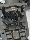
When you remove the 3 screws on the retainer plate you will find the wire pads are marked as VCC, GND, and PWM. The first image shows the normal board locations for the other end of each wire.
This document may be also useful to provide general information: CGo3 Removing the Three Black Wires