Hello my friend,He decidido tomarme el tiempo para probarlo. Puede que tengas que venir a protegerme de la ira de mi mujer, que no está muy contenta conmigo ahora.
El GUI funciona bien con el motor desenchufado. El motor no se ha parado después de unos segundos. Lo dejé funcionar durante un rato.
Había desenchufado el Motor #1. Había suficiente cable disponible para conectar el Motor #4 al ESC del Motor #1. Eso también funcionó sin problema. El motor #4 funciona en sentido contrario a las agujas del reloj cuando se conecta normalmente al ESC #4. Funcionó en el sentido de las agujas del reloj (como se esperaba) cuando se conectó al ESC #1.
I decided to take the time to try it. You may need to come protect me from the wrath of my wife, who is not very happy with me now.
The GUI works fine with a motor unplugged. There was no stopping of the motor after a few seconds. I let it run for awhile.
I had unplugged Motor #1. There was enough wire available to connect Motor #4 to the Motor #1 ESC. That also worked without problem. Motor #4 runs counter clockwise when normally connected to ESC #4. It ran clockwise (as expected) when connected to ESC #1.

Sorry to hear that your wife is not very happy with your hobby.
I just tried the GUI without engine 3 as well and it works without a problem. I have tried the other engines and they work as expected.
I then switched motor 1 (in perfect condition) to motor 3 position, tested it and it responds the same as motor 3, ie erratically.
Question: does this mean that ESC 3 is failing?
Something I didn't do is to test motor 3 (supposedly damaged) in the position of motor 1.
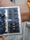
I will do that tomorrow when I manage to get the main board out with the proper tool that I don't have right now, so I can visually check for any obvious damage, if I manage to identify the ESCs.
Greetings
Translated with www.DeepL.com/Translator (free version)