Hello Fellow Yuneec Pilot!
Join our free Yuneec community and remove this annoying banner!
Sign up

Q500 4K No GPS Lock, No GUI

I would try the following thins one by another:
- Connect copper foil to ground to have better shield against interferences between camera WiFi and GPS receiver. or impfove shielding with a second copper foil inside the body around the camera location.
- A ferrit core on the power wires between mainboard and camera connector.
- Put the compass away from the camera and test it.
- From Blade 350QX I know about a problem with power supply (but on the 5V rail). GPS module is connected to 5V. To overcome this problem an additional codensator 100myF (low ESR) was used. Maybe the same may help on Q500 mainboard.
Here is the location at 350's mainboard:
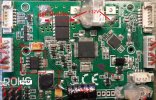
350QX_MB_Elko.jpg
Q500 mainboard is nearly the same.

br HE
 
There is not much pedigree to these voltage values. But it is all I have to offer.

Have you been using the same battery for all checks on both drones? Do you have another battery (or a power supply) you can use to see if the battery may be an issue?
Thanks WTFD.

Yes, I have a total of four useful batteries and they all have had their turn powering up the drone, Also external DC power sources on the bench with variable voltage and amp output.

I have not tried powering the camera off the drone yet, I can see where that would probably make things work but would still leave us in the dark regarding the main V-drop issue if that is the cause. Can't wrap my head around [the problem] being frequency oscillation related but at this point who knows.
 
Last edited:
I would try the following thins one by another:
- Connect copper foil to ground to have better shield against interferences between camera WiFi and GPS receiver. or impfove shielding with a second copper foil inside the body around the camera location.
- A ferrit core on the power wires between mainboard and camera connector.
- Put the compass away from the camera and test it.
- From Blade 350QX I know about a problem with power supply (but on the 5V rail). GPS module is connected to 5V. To overcome this problem an additional codensator 100myF (low ESR) was used. Maybe the same may help on Q500 mainboard.
Here is the location at 350's mainboard:
View attachment 27659
Q500 mainboard is nearly the same.

br HE
Will try that. Yesterday evening I thought of dismantling it all out on the bench, motors and all and try starting it up without the shell, shield, etc., extending the compass module out of the way and everything else that might cause interference, Will also look into the low ESR cap.

So, I forgot about testing the pin output to the camera! If we have 5v at the pins, their is voltage regulation circuitry providing 5v to the camera...hmm.
 
Last edited:
On the other hand, the camera may be feeding directly off the battery and that would cross out any voltage regulation and I am using a brand new 7500mAh battery for power.
The camera power and ground are from the pads for the motor power leads. The PWM is from a transistor near the left rear of the board.
Q500 General Mainboard
Q500 “Power ON” Study
Q500 Series Camera Tilt Transistor

I'm still puzzled by the coincidence of your situation. You are experiencing a very rare problem, and you have two concurrent examples. This situation literally screams "common factor" somewhere. Did both drone kits come from the same seller?
 
  • Like
Reactions: DoomMeister
Thanks WTFD,

I know it seems rare, but there are other flyers who are also experiencing this same exact issue with their Q500. There has to be a logical explanation for this.

Did some more testing this morning, I should definitely carry out my testing in the morning when my head is clear.

- I got to power the camera off the drone and guess what, it powers up and the drone actually locks perfectly.
- This tells me that there is some kind of interference between the electronics of the camera and the electronics off the drone, or electromagnetic interference caused by wiring? Could it be that [edited]...the power of the camera's transmission signal has been altered in a way that incapacitates the on-board GPS? And how is/was this interference created. Is it something that happens when one drops a Q500 out of the sky or gets hit hard on the ground. Coincidentally both Q's had preiously dropped from the sky. Bad purchase choice on my part, but again the guy in the Y/T video has the same issue but no mention of having his drone previously failing or dropping out of the sky as well as at least two other Q500 flyers who posted comments below on the video, stating they experienced the same problem.
- BTW, I did place the remotely powered camera next to the nose of the Q500, it STILL locked GPS, so all of the above regarding WiFi interference may be thrown out the window.

There are no missing parts, all parts check out to be working...GUI/the electrical wiring side/parts replacements/manual-visual board inspections...AND two separate examples (from different sellers) with the same exact issue when camera is removed, but now work and lock GPS when the camera is remotely powered, turning on all of their motors and seemlesly operate on my controller command, with camera video and all working.

:(
 
Last edited:
- This tells me that there is some kind of interference between the electronics of the camera and the electronics off the drone, or electromagnetic interference caused by wiring? Could it be that [edited]...the power of the camera's transmission signal has been altered in a way that incapacitates the on-board GPS?

:(
These pictures might give you some ideas of where to check for interferences or unexpected voltage drops.
Power Taps .jpgInside front.jpgOutside Front.jpgQ500 GPS Module Connections.jpgJumper2.jpg

Since the problem does not occur when the camera is powered from another source, I would doubt the camera transmission signal is the issue. But that is just an amateur's observation. There are other members that could make more informed statements regarding that possibility.
 
Last edited:
Thanks for these images, I'm disassembling everything this next week down to the last screw as I was able to track down a pair of new body shells, upper and lower for a good price, so this bird is on it's way to flying status. this will provide me the experience to transfer everything that's internal to the new body. Something has to come out of this deal I definitely know I'm missing/overlooking something, be it in the wiring or shielding. At least it seems to be interference and not a bad motherboard...knock on wood and my fingers crossed.

Something has to have shifted or wrongly placed inside the body during the period these birds were previously rebuilt (what are the chances two flyers, two drones, placed the wiring back the wrong way creating some kind of interference) and that's my current guess, it has to do with wiring.

Would there be anything that a rebuilder might have discarded as unuseful, a small piece of shielding material glued to the body frame and not carried over to the new shell aside the bigger shield over the main board?...or a small EM trap on any wire?
 

Attachments

  • E-Purchase.jpg
    E-Purchase.jpg
    261.9 KB · Views: 5
Last edited:
Update,

The surgery and transplant has begun. I received the body shells earlier than expected so I started the swap yesterday evening. WTFD, I'll be adding my voltage readings on the boards so as to have additional confirmation/information, hope that's useful to someone. Off the bat, I found the receiving or transmitting antenna is lurking just on top next to the back of the hotshoe, I'll relocate to somewhere on the side and see how the GPS reacts, everything else "unfortunately" looks good upfront. And the burning smell I got from one motor on the first day I turned it on, I found the cause.

This is my first attempt at resurrecting a drone and I'm sure you are all tired of looking at stuff like this, please excuse the little kid in me trying to fix his tricycle, lol.
 

Attachments

  • IMG_1594.jpg
    IMG_1594.jpg
    1.3 MB · Views: 7
  • IMG_1591.jpg
    IMG_1591.jpg
    1.3 MB · Views: 7
  • IMG_1601.jpg
    IMG_1601.jpg
    1.3 MB · Views: 7
  • IMG_1598.jpg
    IMG_1598.jpg
    1.3 MB · Views: 7
  • IMG_1595.jpg
    IMG_1595.jpg
    1.3 MB · Views: 7
  • IMG_1585.jpg
    IMG_1585.jpg
    1.5 MB · Views: 7
  • IMG_1584.jpg
    IMG_1584.jpg
    1.2 MB · Views: 6
Last edited:
  • Like
Reactions: WTFDproject
Questions regarding the wire antennas coming out of the receiver module:

- Is there a reason that Yuneec engineers placed one antenna wire at the front end of the drone and the other antenna placed on the left wing of the drone close to the receiver?
- Would it matter if I redirected the antenna that sits on the nose next to the compass and place it along the right wing of the drone similar to the one at the left wing?

I'm putting everything back together and my feeling is that it would be better this way. I would need to check the length of the front antenna wire or also reposition the receiver module so this setup can work.
Those antennas need to be at a 90 degree angle to each other. As the drone is positioned differently in respect to the ground station one or the other will have better signal reception. The one with better reception (better signal to noise ratio) will be the one used. If they were positioned in a straight line there would be a position where you would be looking down the wire instead of from the side and the signal would be close to nil from both antennas.
 
Exactly what I needed to know at this point DM, thank you. I can get the rest of the rebuild moving.
 
Have another question about somehting I was not expecting to hold me back:

How do I go about extracting the four rubber motor mounts without breaking them? I tried pulling while I pushed some of the round rubber from the other side, but that does not seem to be doing anything to get them off and feels like I'm actually breaking the seal.

Would I need to buy new ones or should I just pull on them to make them snap off?
 

Attachments

  • IMG_1610.jpg
    IMG_1610.jpg
    1.2 MB · Views: 4
  • IMG_1614.jpg
    IMG_1614.jpg
    1.2 MB · Views: 4
Have another question about somehting I was not expecting to hold me back:

How do I go about extracting the four rubber motor mounts without breaking them? I tried pulling while I pushed some of the round rubber from the other side, but that does not seem to be doing anything to get them off and feels like I'm actually breaking the seal.

Would I need to buy new ones or should I just pull on them to make them snap off?
There were some variations:
If you have the type that are a large ring on the motor side and four washers on the screw head side, you should be able to pull the large washer off, then push the small washers out through the hole.
Mount.jpg

If there is a plastic tube in each of the four holes, push the tubes out first. Then use the above method if the washers are divided.
If the washers are not divided, push in from the edge on the screw head side and down through the hole at the same time.
 
Once again, you were spot on. I was being a sissy about it, got up early this morning and I pushed them out harder and got all four off in 2 minutes. I appreciate the dedication you guys put into this forum day and night helping others get on their feet. I'm learning alot reading from all the issues good and bad, more into signal loss which is scary and how you read all the telemetry data and call out what happened, it's really impressive to me how far this "hobby" has gone and this is already 7-8 year old drone technology on this Q500 available to the consumer, I can only guess how many decades ahead military versions of these things are with current non-commercially available technology.
 

Attachments

  • IMG_1615.jpg
    IMG_1615.jpg
    1.1 MB · Views: 4
  • Like
Reactions: WTFDproject
Success!

After going through every set of wires, cables, motors, boards, putting the screws on both shells and thirty seven posted messages later.,.I decided it was time to go outside and turn the remote control and the bird ON and happy to report that I have just been able to pair the drone and lock GPS with the camera powered-on, on the hotshoe. What a relief!

I cannot say I am100% certain what cured the NO-GPS condition, but I did remove the receiver's front antenna out of the way of the hotshoe (it was on top of the hotshoe) and tagged it one inch to the left side of the body. Everything else was transplanted EXACTLY as found or it came from the factory, wire loops and all, no extra shielding was added on purpose.

Thanks WTFD, h-elsner, DoomMeister and others for sharing knowledge, I've learned a lot on the Q500 and a long list of other things also. I'll go over the voltage readings after I take care of the other Q500 and rearrange the antenna and see what happens there.
 
Last edited:

New Posts

Members online

Forum statistics

Threads
20,955
Messages
241,599
Members
27,284
Latest member
csandoval