Hello Fellow Yuneec Pilot!
Join our free Yuneec community and remove this annoying banner!
Sign up

Typhoon H binding problem. No orange lights

Joined
Mar 28, 2023
Messages
10
Reaction score
3
Age
24
My copter does not go into bind mode.
Following the binding verification pdf I get stuck on step 38. The rear led keeps blinking blue fast. And after tilting a while it changes to very fast red blinking.
What can I do?
 
My copter does not go into bind mode.
Following the binding verification pdf I get stuck on step 38. The rear led keeps blinking blue fast. And after tilting a while it changes to very fast red blinking.
What can I do?
Keep moving in the procedure. I suspect you have a problem with the rear LED. You may encounter other steps when the rear LED colors will not match what is expected.
If you get the receiver ID displayed at Step 46, you're probably good to go. Just be aware the rear LED is going to get very confusing while trying to fly.
 
After changing antenna on the st16 I managed to bind :))
But my main led changes from solid purple to alternating blinking red and purple and drone beeps twice when changing to this status.
Can't find the meaning of this.
 
To try and verify the Main LED functionality please go through this list of steps.

1) turn on just the aircraft - you should get blue flashing 5 times per second

2) now turn on the ST16 and allow aircraft and camera to connect

3) place the Mode Switch to Smart mode (up) - you should get a flashing or solid green Main LED depending on the state of GPS Acquiring or Ready

4) place the Mode Switch to Angle mode (mid) - you should get purple on the Main LED

5) place the Mode Switch to Home mode (down) - you should get a red flash on the Main LED 5 times per second

This will confirm that all three colors are working on the Main LED board.
Did this and found out that the Green is not working. Any suggestions how to restore?
 
With a new one is the simplest way. They were cheap. Of course, first, trace the wires.
 
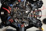
We have found a weak solder joint on the LED board and a quick touch up with flux and solder got it working. The last one was at least a couple of years ago. I’ll see if I can find photos. If not, I’ll pull one from an H480 and try to annotate the photo.
 
  • Like
Reactions: jnmchlmnnn
With a new one is the simplest way. They were cheap. Of course, first, trace the wires.
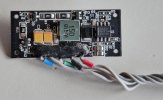
I checked the little board which has the led and that looks all fine. The wires disappear in the battery compartment. Where do they go/connect? How do I get to the other end to check connections?
 
2CD84211-A78D-4133-A9C5-0FFD7656788A.jpeg
You can test the LED itself with a 1.5 V alkaline battery. I’ll pull the board later today and trace the circuit. As I remember there were current limiting resistors from the 5VDC to the positive leads and then a switched ground connected to the negative leads that came from the Main Board.
 
I found that out when I pulled the covers and started tracing circuits.

Any idea what voltage comes from the Mainboard? The 54331 is a Texas Instruments DC-DC Buck Converter that operates with 3.5V to 28V input.
 
I found that out when I pulled the covers and started tracing circuits.

Any idea what voltage comes from the Mainboard? The 54331 is a Texas Instruments DC-DC Buck Converter that operates with 3.5V to 28V input.
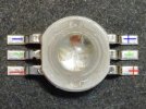
I tested the led directly at the led contacts. And only Red and Blue from the RGB are lighting up. No Green. So that explains my confusing light signals. I will order and replace the main LED unit.

Thanks for the help!
 
Be careful with soldering. These LEDs are very temperature sensitive. The plastic is melting very easily.
 
  • Like
Reactions: Steve Carr
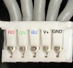
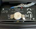
For the component side of the circuit board please refer to the photo in Post #14 from @h-elsner as it has better lighting than the one I took. The 54331 U1 IC and most of the circuitry around it forms a regulated power supply for the board. Voltage from the Main board in the aircraft is supplied to pins 2 (+) and 7 (-) and the supply to the board comes from pin 8. The cable to the Main board has the following pinout.
BE388602-F8BE-4DE8-B26A-BFCEE5D45665.jpeg

The voltage from U1-8 is supplied to the positive terminals of the tricolor LED as shown here.
B33B52A3-C6D3-419C-87F4-675F3CF5BB99.jpeg

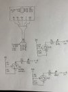
The signals coming from the Main board to select Red, Green, and Blue go through a voltage divider to a G2306 MOSFET and current limiting resistor to the cathode side of the respective LED’s as shown in the following drawing.
1BE5FDE5-ED42-4E3F-9412-263046864399.jpeg

The next time I get into this I’ll take some voltage readings also. Need to do it while using a lighted magnifier. Would be easy to short something out otherwise.
 
Thanks H.E. that saves me the trouble of doing the measurements.
 

New Posts

Members online

No members online now.

Forum statistics

Threads
20,955
Messages
241,598
Members
27,286
Latest member
lahorelaptop