Hello Fellow Yuneec Pilot!
Join our free Yuneec community and remove this annoying banner!
Sign up

Repairing a C23 camera

Joined
Jan 30, 2018
Messages
103
Reaction score
4
Age
45
After discovering that the problems I had were related to a loose cable (TX cable disconnected from the connector board), I thought I would fix it by replacing the entire slip ring.

I had a spare slip ring for the CGO3 but it looks like the part is not the same (it is smaller on the C23) and the general design of the camera appears to be significantly different as well.

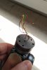
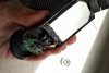
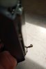
But another thing I discovered when removing the plastic cover of the C23 is that the connection to the clover leaf antenna is broken too. If that's indeed the antenna for the video downstream that would explain why I always had a bad video connection with this camera. Attached are pictures showing the connector that is detached from the board to which it was originally glued/soldered (?).

Now the question is: how could I do a proper repair myself? Any idea?
 

Attachments

  • IMG_20190721_1533493.jpg
    IMG_20190721_1533493.jpg
    2.1 MB · Views: 116
  • IMG_20190721_1520399.jpg
    IMG_20190721_1520399.jpg
    2.2 MB · Views: 117
  • IMG_20190721_1521360.jpg
    IMG_20190721_1521360.jpg
    2.6 MB · Views: 115
Last edited:
Looks very much like this I guess but in my case the pin is still there and it's only the metal circle that I would need to replace.

 
Last edited:
I have not inspected the antenna connection. Does the coax appear to have a U.FL connector on each end or is it soldered onto the antenna?
You may be able to solder the slip ring wires onto the gimbal board so long as the wires are not broken. You will need a picture of the location where the wires should be soldered.
 
I just fixed this one and I put some liquid rubber to keep it in place. I fixed 3 cameras so far with other issues but all 3 have this connector ripped off from the board.
Really bad design the antenna cable is too rigid for that short length.
 

Attachments

  • 20190807_193537_HDR.jpg
    20190807_193537_HDR.jpg
    2.9 MB · Views: 94
  • 20190807_193552.jpg
    20190807_193552.jpg
    2.5 MB · Views: 87
The general design of the H and H Plus is actually quite good for flying but not very forgiving for people that crash them. I really can’t think of a relatively high performance aircraft that was designed to crash.
 
I just fixed this one and I put some liquid rubber to keep it in place. I fixed 3 cameras so far with other issues but all 3 have this connector ripped off from the board.
Really bad design the antenna cable is too rigid for that short length.

Thanks for your feedback ! Based on the pictures I posted, do you think I could repair mine in the same way?
 
In your case you need one of this to be installed
 

Attachments

  • Screenshot_2019-08-20-06-51-42.png
    Screenshot_2019-08-20-06-51-42.png
    1.3 MB · Views: 55
Last edited:
In your case you need one of this to be installed

Thanks for your reply. However, I am a little confused because as can been seen on the pictures I posted, the central pin is still firmly attached to the main board. But the round part is the one that broke off. In the part on the left of your picture, as well as in other parts I have been able to find in online shops, both come together...
 
Thanks for your reply. However, I am a little confused because as can been seen on the pictures I posted, the central pin is still firmly attached to the main board. But the round part is the one that broke off. In the part on the left of your picture, as well as in other parts I have been able to find in online shops, both come together...


I have mine from here 10x IPX U.FL SMD SMT Solder PCB Mount Socket Jack Female RF Coaxial Connector | eBay
You have to desolder the old one from the board and install the new one. If you can solder back your broken piece I think it will work but you need to be sure there it is enough insulation between the center pin and the outer shell.
Otherways you will not have wifi connection. I will rccomend to install a new one and then secure-it with this stuff 50ml T7000 Glue Multipurpose Adhesives Super Glue T-7000 Black Liquid Glues For | eBay
That will prevent a future dettachment from the board.
 
Ok so to do a clean fix, I should desolder the pin and then solder the new part. Given my soldering skills and extremely rudimentary equipment I think I won't trust myself to do that... Maybe I try to find someone who has more experience soldering. Yuneec Germany has apparently transfered the non-guarantee repairs to a third-party company and it looks like they are going to charge me a lot of money for this (and I am not even sure they would do this soldering thing or merely propose to change the board completely, which even if I refuse will leave me with a bill of a few dozens eur).

Thanks a lot for your help anyway.
 
I am sorry. I will do it but since you are not in the states I can't help to much. Only if the cost for shipping both ways is less than what you will pay for the service. I do repairs for cgo3 /+ and c23 and I can help you.
 
Ok so to do a clean fix, I should desolder the pin and then solder the new part. Given my soldering skills and extremely rudimentary equipment I think I won't trust myself to do that... Maybe I try to find someone who has more experience soldering. Yuneec Germany has apparently transfered the non-guarantee repairs to a third-party company and it looks like they are going to charge me a lot of money for this (and I am not even sure they would do this soldering thing or merely propose to change the board completely, which even if I refuse will leave me with a bill of a few dozens eur).

Thanks a lot for your help anyway.


If you can't find anyone to help you I can make a listing on E-Bay with one of mine for say $150 + international shipping and when you receive mine you send me yours back and I will refund you $100 and I will keep $50 for repairing yours. Mine is new. I know the service centers are not that friendly when is coming to charge people.
I just want to help you get back in business.
 

Attachments

  • 20190827_182933.jpg
    20190827_182933.jpg
    1.6 MB · Views: 37
  • 20190827_182958.jpg
    20190827_182958.jpg
    1.6 MB · Views: 34
  • Like
Reactions: Steve Carr
Thank you so much, your help on this is really appreciated. I am talking to some company that repairs electronic stuff and does soldering, if it doesn't work out I'll get back to you! Thanks again :)
 
If you can't find anyone to help you I can make a listing on E-Bay with one of mine for say $150 + international shipping and when you receive mine you send me yours back and I will refund you $100 and I will keep $50 for repairing yours. Mine is new. I know the service centers are not that friendly when is coming to charge people.
I just want to help you get back in business.

I found a company that can do the soldering. However, I still need to reconnect (solder) the wires to the gimbal connector (the tiny plate that is screwed to the top part of the vibration-isolating thing) , would you be able to help me with the wiring as I am not sure if I remember?

Attached is a picture where the part in question is visible inside a black circle drawn over the screenshot. Just for the sake of clarity, I know the illustration is for a CGO3 but I am still talking about the wiring of the C23.
 

Attachments

  • typhoon_H_connector_part_LI.jpg
    typhoon_H_connector_part_LI.jpg
    706.4 KB · Views: 53
I found a company that can do the soldering. However, I still need to reconnect (solder) the wires to the gimbal connector (the tiny plate that is screwed to the top part of the vibration-isolating thing) , would you be able to help me with the wiring as I am not sure if I remember?

Attached is a picture where the part in question is visible inside a black circle drawn over the screenshot. Just for the sake of clarity, I know the illustration is for a CGO3 but I am still talking about the wiring of the C23.


OK, here it is the order of those wires. If you need a new cable let me know.
 

Attachments

  • 20190902_114638_HDR.jpg
    20190902_114638_HDR.jpg
    2 MB · Views: 43
  • 20190902_114708_HDR.jpg
    20190902_114708_HDR.jpg
    2 MB · Views: 37
  • 20190902_114714_HDR.jpg
    20190902_114714_HDR.jpg
    2 MB · Views: 39
Thanks again, I have rewired the camera but it was making horrible sounds... It seems like the top circular part was not in the correct position when I screwed it back to the plastic plate...
Is there any rule to follow?
 
Thanks again, I have rewired the camera but it was making horrible sounds... It seems like the top circular part was not in the correct position when I screwed it back to the plastic plate...
Is there any rule to follow?


Can you explain what that sound was like. was beeping? You can post a video here.
 
I apologize for the lack of reply, I had no time to get back to this. Here is a video
After unscrewing the camera from the plastic part and making one or two full turns, it has vastly improved but I still hear that kind of noise from time to time.
But what I don't understand is that there seems to be now way to identify the correct position to screw it. I mean, if you are, say, a quarter turn off, then the default position of the camera when starting the drone will be either left or right. Am I missing something obvious here?
Thanks again
 
Yes, there are no marks in the yaw motor or the plate to tell you where is the right position. I always use a marker when I disassemble these cameras to remember how it was. I see from the video you get-it right now.
About the noise, I can't help too much because you are not here in the area. But you can check if the camera is put some resistance when is without power in the pitch motor. Move the camera all the way up and down and see where have some resistance.
If it's moving freely all the way up and down there is something else. Most of the time are because of that motor.
 

New Posts

Members online

Forum statistics

Threads
20,980
Messages
241,854
Members
27,402
Latest member
Ludwig