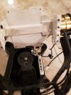
Alas another crash. Fortunately I have one more Blade Chroma Body and the Drone works. The CGO3 is a different story.
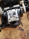
The CG03 Gimbal sustained damage. The white plastic plate (optical table) that holds the lens and other circuit board broke (it should be made of aluminum). I was able to epoxy the optical table together to functional. The camera itself works (binds and a image appears on the ST10).
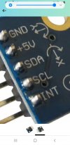
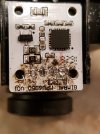
The issue is that in the process of disassembly the 4 wires that attach to the Gimbal MPU6050 detached and I do not know the pin out so I can resholder them.
The four wires originate from the motherboard through the same connector. I can identify positions of the wires in relation to the connector to the motherboard using a continuity tester, but where they attach to the MPU6050 is the mystery. The wire attached in the first photo is probably incorrect in that I attached it after the fact.
Any help would be greatly appreciated.
The CG03 Gimbal sustained damage. The white plastic plate (optical table) that holds the lens and other circuit board broke (it should be made of aluminum). I was able to epoxy the optical table together to functional. The camera itself works (binds and a image appears on the ST10).
The issue is that in the process of disassembly the 4 wires that attach to the Gimbal MPU6050 detached and I do not know the pin out so I can resholder them.
The four wires originate from the motherboard through the same connector. I can identify positions of the wires in relation to the connector to the motherboard using a continuity tester, but where they attach to the MPU6050 is the mystery. The wire attached in the first photo is probably incorrect in that I attached it after the fact.
Any help would be greatly appreciated.
Attachments
Last edited: